3.0 INSTALLATION INSTRUCTIONS
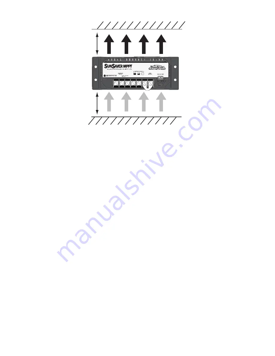
WARM AIR
COOL AIR
AT LEAST
6” (150 mm)
AT LEAST
6” (150 mm)
Figure 3. Mounting and cooling
Step 3: Mark Holes
Use a pencil or pen to mark the four (4) mounting hole
locations on the mounting surface.
Step 4: Drill Holes
Remove the controller and drill 3/32” (2.5 mm) holes in the
marked locations.
Step 5: Secure Controller
Place the controller on the surface and align the mounting
holes with the drilled holes in step 4. Secure the controller in
place using the mounting screws (included).


