background image

MORNINGSTAR CORPORATION

37

 4.0

4.5 Protections

Solar Overload

(No LED indication) The SunSaver MPPT will limit battery 

current to the 15 Amp maximum rating. An over-sized 

solar array will not operate at peak power. The solar array 

should be less than the SS-MPPT 

nominal max. input power 

rating

 for optimal performance. See 

Section 7.0 Technical 

Specifications

 for more information.

Load Overload 

(Battery Status LEDs: R/Y-G sequencing) If the load 

current exceeds the maximum load current rating, the SS-

MPPT will disconnect the load. The greater the overload the 

faster the load will be disconnected. A small overload could 

take a few minutes to disconnect.

The SS-MPPT will attempt to reconnect the load two (2) 

times. Each attempt is approximately 10 seconds apart. If 

the overload remains after two (2) attempts, the load will 

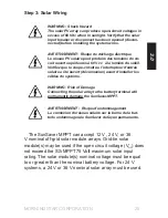
remain disconnected until power is removed and reapplied.

Solar Short Circuit 

(Charging Status LED: OFF) Solar input power wires are 

short-circuited. Charging automatically resumes when the 

short is cleared.

Load Short Circuit

(Battery Status LEDs: R/Y-G sequencing) Fully protected 

against load wiring short-circuits. After two (2) automatic 

load reconnect attempts (10 seconds between each 

attempt), the fault must be cleared by removing and 

reapplying power.

Summary of Contents for SUNSAVER MPPT Series

Page 1: ...1098 Washington Crossing Road Washington Crossing PA 18977 USA www morningstarcorp com Installation and Operation Manual SUNSAVERMPPT TM WITH TRAKSTARTM MPPT TECHNOLOGY Model SS MPPT 15L ...

Page 2: ...full technical specifications Array voltage should never exceed maximum input voltage Refer too the solar module documentation to determine the highest expected array Voc as defined by the lowest expected ambient temperature for the system location These power levels refer to the maximum wattage the SS MPPT 15L can process Higher power arrays can be used without damaging the controller but efficie...

Page 3: ...1 General Installation Notes 15 3 2 Configuration 16 3 3 Mounting 19 3 4 Wiring 21 4 0 Operation 28 4 1 LED Indications 28 4 2 TrakStarTM MPPT Technology 30 4 3 Battery Charging Information 33 4 4 Load Control Information 35 4 5 Protections 37 4 6 Inspection and Maintenance 39 4 7 Programming Custom Setpoints 40 5 0 Troubleshooting 41 5 1 Error Indications 41 5 2 Common Problems 42 6 0 Warranty 43...

Page 4: ...eration of the controller NOTE Indicates a procedure or function that is important for the safe and proper operation of the controller General Safety Information Read all of the instructions and cautions in the manual before beginning installation There are no user serviceable parts inside the SunSaver MPPT Do not disassemble or attempt to repair the controller Disconnect all sources of power to t...

Page 5: ... perform any servicing other than that specified in the operating instructions unless you are qualified to do so WARNING EXPLOSION HAZARD DO NOT DISCONNECT WHILE CIRCUIT IS LIVE UNLESS AREA IS KNOWN TO BE NON HAZARDOUS CAUTION To reduce the risk of fire connect only to a circuit provided with a maximum branch circuit overcurrent protection rating not to exceed the model current rating on page 2 an...

Page 6: ... UN INCENDIE OU À UNE EXPLOSION PROVENANT DE GAZ REJETÉS DANS L AIR VEUILLEZ PRENDRE LES PRÉCAUTIONS NÉCESSAIRES AVERTISSEMENT Ces instructions d entretien sont exclusivement réservé es à des techniciens qualifiés Pour réduire le risque de choc électrique ne réalisez aucun entretien autre que celui stipulé dans les instructions de fonctionnement à moins que vous ne possédiez les qualifications néc...

Page 7: ...ink can become very hot during operation Use insulated tools when working with batteries Avoid wearing jewelry during installation The battery bank must be comprised of batteries of same type make and age Do not smoke in the vicinity of the battery bank Mount the controller at least 3 ft 1 m away from vented bat teries unless separated by a barrier or located in a separate compartment Power connec...

Page 8: ...auffe excessive d une connexion desserrée Utilisez des conducteurs et des coupe circuits de dimensions adaptées Ce contrôleur de charge ne doit être connecté qu à des circuits en courant continu Ces connexions CC sont identifiées par le symbole ci dessous Le contrôleur SunSaver doit être installé par un technicien qualifié conformément aux règlementations électriques du pays où est installé le pro...

Page 9: ... performance Self diagnostics and electronic error protection prevent damage when installation mistakes or system faults occur The controller also features four 4 settings switches for adjustability a meter port and terminals for remote battery temperature measurement optional Using MSViewTM PC software the SS MPPT can be programmed with custom settings to function as a lighting controller to turn...

Page 10: ... provided Figure 1 SunSaver MPPT features 1 Status LED An LED indicator that shows charging status and also indicates when a solar input fault condition exists 2 Power Terminal Block Power terminations for system Solar Battery and Load connections 3 Battery Select Jumper A removable jumper to select the battery type 1 2 8 7 6 5 4 3 ...

Page 11: ... optional to remotely monitor battery temperature NOTE The use of a Remote Temperature Sensor is strongly recommended Controller location air flow and system power can drastically affect the local temperature sensor reading A RTS will provide optimal charging performance 7 Local Temperature Sensor Measures ambient temperature Battery regulation is adjusted based on ambient temperature unless an op...

Page 12: ...re sensor reading A RTS will provide optimal charging performance Remote Meter Model RM 1 The digital Remote Meter displays system operating information error indications and self diagnostic read out Information is displayed on a backlit 4 digit custom LCD display The large numerical display and icons are easy to read and large buttons make navigating the meter menus easy Additionally a status LED...

Page 13: ...and EN60335 2 29 battery chargers A means shall be provided to ensure all pole disconnection from the power supply This disconnection shall be incorporated in the fixed wiring Using the SunSaver MPPT grounding terminal in the wiring compartment a permanent and reliable means for grounding shall be provided The clamping of the earthing shall be secured against accidental loosening The entry opening...

Page 14: ...ce with the instruction manual may cause harmful interference to radio communication However there is no guarantee that interference will not occur in a particular installation If this equipment does cause harmful interference to radio or television reception which can be determined by turning the equipment on and off the user is encouraged to try to correct the interference by one or more of the ...

Page 15: ...ntilation to release the gasses Do not install in locations where water can enter the controller Loose power connections and or corroded wires may result in resistive connections that melt wire insulation burn surrounding materials or even cause fire Ensure tight connections and use cable clamps to secure cables and prevent them from swaying in mobile applications Only charge lead acid or NiCd bat...

Page 16: ... See Section 7 0 Technical Specifications for detailed charging information for each battery type The battery select jumper is secured in the terminal block between terminal 6 and terminal 7 as shown in figure 2 The second column in table 1 specifies whether the jumper should be removed or remain in place depending on the desired battery type Battery Type Battery Jumper Switch 1 Gel1 INSERTED ON S...

Page 17: ...e modified with custom programming See Section 4 7 Programming Custom Setpoints for more information Enable or Disable Auto Equalization Turn the auto equalize feature OFF or ON The auto equalize feature will administer an equalization charge flooded battery type only every 28 days or if the battery discharges too low the previous night There is no equalization charge for the gel or sealed battery...

Page 18: ...h a PC2 and Morningstar s MSView software MODBUS is an open communication protocol standard used by Morningstar s MSView PC software and other 3rd party hardware software SWITCH 4 OFF MORNINGSTAR REMOTE METER SWITCH 4 ON MODBUS PROTOCOL FOR MSVIEW 3RD PARTY DEVICES 2 Morningstar PC Meterbus Adapter Model MSC required Not included See Morningstar s website for more information www morningstarcorp c...

Page 19: ...e enceinte avec des batteries à évent à électrolyte liquide Les vapeurs des batteries sont inflammables et corroderont et détruiront les circuits du SunSaver PRUDENCE Endommagement de l équipement Assurez une ventilation suffisante en cas d installation du SunSaver MPPT dans une enceinte L installation dans une enceinte hermétique entraîne une surchauffe et une réduction de la durée de vie du prod...

Page 20: ...en to mark the four 4 mounting hole locations on the mounting surface Step 4 Drill Holes Remove the controller and drill 3 32 2 5 mm holes in the marked locations Step 5 Secure Controller Place the controller on the surface and align the mounting holes with the drilled holes in step 4 Secure the controller in place using the mounting screws included ...

Page 21: ...th Article 690 of the latest edition of the National Electric Code NFPA 70 NOTE The total current draw of all system loads connected to the SunSaver MPPT LOAD terminals cannot exceed the controller s load current rating NOTE For mobile applications be sure to secure all wiring Use cable clamps to prevent cables from swaying when the vehicle is in motion Unsecured cables create loose and resistive ...

Page 22: ...the system load s or load distribution panel as shown in figure 4 Refer to the wire gauge chart on page 41 of this manual for correct wire size If required the negative load connection may be earth grounded Use appropriate gauge wire and proper grounding methods for the installation site An in line fuse holder should be wired in series in the load positive wire as shown DO NOT INSERT A FUSE AT THI...

Page 23: ...es conducteurs du système mis à la terre Seuls les dispositifs GFDI sont autorisés à déconnecter les conducteurs reliés mis à la terre 6 in 150 mm MAX BATTERY NEGATIVE BATTERY POSITIVE 25 AMP FUSE 12V 24V BATTERY EARTH GROUND Figure 5 Battery wiring Before connecting the battery measure the battery voltage It must be over 7 volts to power the controller For 24 volt systems the battery voltage must...

Page 24: ...f this manual for correct wire size If required the negative battery connection may be earth grounded Use appropriate gauge wire and proper grounding methods for the installation site Wire an in line fuse holder no more than 6 inches 150 mm from the battery positive terminal DO NOT INSERT A FUSE AT THIS TIME ...

Page 25: ... a été ouvert déconnexion avant d installer les câbles du système WARNING Risk of Damage Connecting the solar array to the battery terminal will permanently damage the SunSaver MPPT AVERTISSEMENT Risque d endommagement La connexion du réseau solaire sur la borne de la bat terie endommagera le SunSaver de façon permanente The SunSaver MPPT can accept 12 V 24 V or 36 V nominal off grid solar module ...

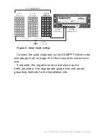
Page 26: ...TIVE SOLAR NEGATIVE 36 V NOMINAL MAX EARTH GROUND Connect the solar module s to the SS MPPT Refer to the wire gauge chart on page 41 of this manual for correct wire size If required the negative solar connection may be earth grounded Use appropriate gauge wire and proper grounding methods for the installation site ...

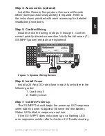
Page 27: ...larity at each connection Verify that all seven 7 SS MPPT power terminals are tightened Figure 7 System Wiring Review 2 1 3 Step 6 Install Fuses Install a 25 Amp DC rated fuse in each fuse holder in the following order 1 Load circuit 2 Battery circuit Step 7 Confirm Power up The SS MPPT should begin the power up LED sequence when battery power is applied Observe that the Battery Status LEDs blink ...

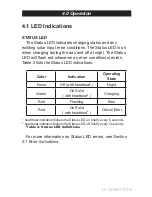
Page 28: ...on s exists Table 2 lists the Status LED indications Color Indication Operating State None Off with heartbeat Night Green On Solid with heartbeat Charging Red Flashing Error Red On Solid with heartbeat2 Critical Error heartbeat indication flickers the Status LED on briefly every 5 seconds heartbeat indication flickers the Status LED off briefly every 5 seconds Table 2 Status LED definitions For mo...

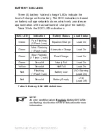
Page 29: ...ion Battery Status Load Status Green Fast Flashing 2 Flash sec Equalize Charge Load On Green Med Flashing 1 Flash sec Absorption Charge Load On Green Slow Flashing 1 Flash 2 sec Float Charge Load On Green On solid Nearly Full Load On Yellow On solid Half Full Load On Red Flashing 1 Flash sec Battery Low LVD Warning Load On Red On solid Battery Empty LVD Load Off Table 3 Battery SOC LED definitions...

Page 30: ... flowing out to the battery The SS MPPT does not create current Rest assured that the power into the SS MPPT is the same as the power out of the SS MPPT Since power is the product of voltage and current Volts x Amps the following is true 1 Power Into the SS MPPT Power Out of the SS MPPT 2 Volts In x Amps In Volts Out x Amps Out assuming 100 efficiency losses in wiring and conversion exist If the s...

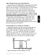
Page 31: ...input voltage results in lower solar input current for a given input power High voltage solar input strings allow for smaller gauge solar wiring This is especially helpful for systems with long wiring runs between the solar array and the SS MPPT An Advantage Over Traditional Controllers Traditional controllers connect the solar module directly to the battery when recharging This requires that the ...

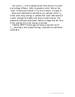
Page 32: ...use Traditional controllers do no operate at the Vmp of the solar array energy is wasted that could otherwise be used to charge the battery and power system loads The greater the difference between battery voltage and the Vmp of the module the more energy is wasted TrakStar MPPT technology will always operate at the Vmp resulting in less wasted energy compared to traditional controllers ...

Page 33: ...Bulk Charge In this stage the battery voltage has not yet reached absorption voltage and 100 of available solar power is used to recharge the battery Absorption When the battery has recharged to the Absorption voltage setpoint constant voltage regulation is used to prevent heating and excessive battery gassing Float After the battery is fully charged the SS MPPT reduces the battery voltage to a fl...

Page 34: ...uipment Damage Excessive overcharging and gassing too vigorously can damage the battery plates and cause shedding of active material from the plates An equalization that is too high or for too long can be damaging Review the requirements for the particular battery being used in your system AVERTISSEMENT Risque d explosion Les batteries à évent et compensation produisent des gaz explosifs Le groupe...

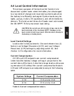
Page 35: ...control circuit may result Wire inverters directly to the battery or battery bank Load Control Settings Load control is fully automatic Choose between two 2 factory Low Voltage Disconnect LVD and Low Voltage Reconnect LVR settings by adjusting switch 2 See Section 3 2 Configuration for more information Current Compensation All LVD and LVR setpoints are current compensated Under load the battery vo...

Page 36: ...tus LED indication will be displayed General Load Control Notes A 15 V maximum regulation voltage limit 30 V 24 V nominal exists for all battery types This limit ensures that the battery and load terminal voltages will never exceed 15 V 30 V This protects certain DC loads that may be damaged by high input voltage Do not wire multiple SunSaver MPPT load outputs together in parallel to power DC load...

Page 37: ... greater the overload the faster the load will be disconnected A small overload could take a few minutes to disconnect The SS MPPT will attempt to reconnect the load two 2 times Each attempt is approximately 10 seconds apart If the overload remains after two 2 attempts the load will remain disconnected until power is removed and reapplied Solar Short Circuit Charging Status LED OFF Solar input pow...

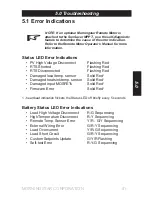
Page 38: ... to avoid over or under charging This is a critical error Contact your authorized Morningstar dealer for service Damaged Internal Temperature Sensor Charging Status LED R on solid The internal heatsink temperature sensor is damaged This is a critical error Contact your authorized Morningstar dealer for service High Temperature Battery Status LED R Y sequencing The heatsink temperature has exceeded...

Page 39: ...ce tasks are recommended at least two times per year for best controller performance Tighten all terminals Inspect for loose broken or corroded connections Verify that all wire clamps and tie downs are secure Check that the controller is mounted in a clean protected environment free of dirt insects nests and corrosion If applicable check enclosure ventilation and air flow holes for obstructions Ve...

Page 40: ...r free on our website at http www morningstarcorp com A setup wizard will guide you through the set point configuration process Refer to MSView help files for more information To use custom set points the Settings Switches must be adjusted as follows SWITCH 1 ON TO USE CUSTOM CHARGING SET POINTS USE THE BATTERY SELECT JUMPER TO SELECT BETWEEN TWO SETS OF CUSTOM CHARGING SET POINTS SWITCH 2 ON TO U...

Page 41: ... RTS Disconnected Flashing Red Damaged local temp sensor Solid Red1 Damaged heatsink temp sensor Solid Red1 Damaged input MOSFETs Solid Red1 Firmware Error Solid Red1 1 heartbeat indication flickers the Status LED off briefly every 5 seconds Battery Status LED Error Indications Load High Voltage Disconnect R G Sequencing High Temperature Disconnect R Y Sequencing Remote Temp Sensor Error Y R G Y S...

Page 42: ... MPPT is not charging the battery Solution If the Status LED is solid or flashing red see Section 5 1 Error Indications If the Status LED is off measure the voltage across the Solar input terminals of the SS MPPT Input voltage must be greater than battery voltage Check fuses and solar wiring connections Check solar array for shading Full testing documentation is available on our website at http su...

Page 43: ...ingstar will pay the return shipping charges if the repairs are covered by the warranty WARRANTY EXCLUSIONS AND LIMITATIONS This warranty does not apply under the following conditions Damage by accident negligence abuse or improper use PV or load currents exceeding the ratings of the product Unauthorized product modification or attempted repair Damage occurring during shipment THE WARRANTY AND REM...

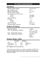
Page 44: ... Battery Charging Regulation Method 4 stage Temp Compensation Coefficient 5 mV C cell 25 C reference Temp Compensation Range 30 C to 60 C Temp Compensated Setpoints Absorption Float Equalize Battery Status LEDs Falling V Rising V G to Y 12 1 13 1 Y to G Y to Flash R 11 7 12 6 Flash R to Y Flash R to R 11 5 12 6 R to Y Note Multiply x2 for 24 Volt systems These power levels refer to the maximum wat...

Page 45: ... 30 V Low Voltage Disconnect2 11 5 V 11 0 V Low Voltage Reconnect2 12 6 V 12 1 V 1 Not temperature compensated 15 V 12 V nominal 30 V 24 V nominal 2 Adjustable by switch not temperature compensated 11 0 V 12 1 V setting can be modified in custom settings NOTE Temperature compensation increases regulation voltage in cold temperature A 15 V 30 V 24 V nominal maximum battery voltage limit prevents da...

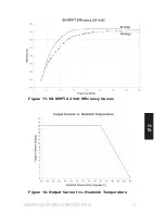
Page 46: ... mm2 Terminal Diameter 0 210 in 5 4 mm Power terminals torque max 35 in lb 4 Nm RTS terminals wire size max Wire gauge min 22 AWG 0 3 mm2 Wire gauge max 12 AWG 3 0 mm2 RTS terminals torque max 0 4 Nm 3 5 in lb Dimensions see inside front cover Weight 1 3 lbs 0 60 kg Efficiency and Deratings Figure 10 SS MPPT 12 Volt Efficiency Curves ...

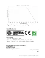
Page 47: ...MORNINGSTAR CORPORATION 47 7 0 Figure 11 SS MPPT 24 Volt Efficiency Curves Figure 12 Output Current vs Heatsink Temperature ...

Page 48: ...ions EMC Directives Immunity EN61000 6 2 1999 Emissions EN55022 1994 with A1 and A3 Class B1 Safety EN60335 1 and EN60335 2 29 battery chargers Specifications subject to change without notice Designed in the U S A Assembled in Taiwan 2013 Morningstar Corporation MS ZMAN SSPPT C v03 ...

Page 49: ... One way Wire Distance meters Wire Gauge mm2 14 12 10 8 6 2 0 3 0 5 0 8 0 13 0 2 140 224 360 574 912 43 68 110 175 278 4 70 112 180 286 456 21 34 55 87 139 8 36 56 90 144 228 11 17 27 44 69 12 24 38 60 96 152 7 12 18 3 29 46 15 18 30 48 76 122 5 9 15 23 37 3 Voltage drop Annealed copper wire at 20 C 36 Volt Nominal Wire Chart amps One way Wire Distance feet Wire Gauge AWG One way Wire Distance met...

Reviews: