background image

TABLE  OF  CONTENTS

1.0 Important Safety Instructions 

4

2.0 Getting Started 

8

2.1  Overview 

8

2.2  Regulatory Information 

10

2.3  Versions and Ratings 

11

2.4   Features 

12

2.5  Optional Accessories 

15

3.0 Installation 

     16


3.1  General Information 

16

3.2  Wiring Zones  

17

3.3  Conduit Knock-outs and Wire Routing 

19

3.4 


Controller 

Installation         

21

4.0 Operation 


            39


4.1 Using the Transfer Switch                                                                                         39   


4.2 TrakStar

TM


MPPT 

Technology 


40 


4.3  Battery Charging Information  


      41


4.4  GFPD-600V 

Operation 


48


4.5  Push-button 


49 


4.6  LED Indications  and Audible Warnings  


      50  


4.7  Protections, Faults & Alarms 


52

5.0 Networking and Communication 


    55  


5.1 


Introduction 


55 


5.2  Morningstar MeterBus

TM


56


5.3  Serial RS-232 

57


5.4  EIA-485 (formerly RS-485)  


59


5.5  Ethernet 

60

6.0 Testing and Troubleshooting 

64

7.0 Maintenance and Service 

67


7.1 


Important 

Safety 

Instructions 


67


 7.2 


Maintenance 

Schedule 


71

8.0 Warranty and Claim Procedure 

72

9.0 Technical Specifications 

74

Summary of Contents for TriStar MPPT 600V

Page 1: ...roller www morningstarcorp com Solar Wind Battery Charger with TrakStarTM Maximum Power Point Tracking Technology Models TS MPPT 60 600V 48 DB TR TS MPPT 60 600V 48 DB TR GFPD MAXIMUM POWER POINT TRAC...

Page 2: ...15 29 6 80 173 12 80 325 14 17 360 1 15 29 4 50 114 12 80 325 90 23 1 30 33 80 20 1 30 33 2 02 51 1 04 26 90 23 1 30 33 1 04 26 2 02 51 1 30 33 90 23 12 PLACES O 0 21 5 2 60 66 14 03 356 14 17 360 1 0...

Page 3: ...Transfer Switch 39 4 2 TrakStarTM MPPT Technology 40 4 3 Battery Charging Information 41 4 4 GFPD 600V Operation 48 4 5 Push button 49 4 6 LED Indications and Audible Warnings 50 4 7 Protections Fault...

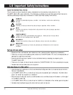
Page 4: ...ion importante pour l utilisation s re et correcte du contr leur Safety Information Read all of the instructions and cautions in the manual before beginning installation There are no user serviceable...

Page 5: ...remain tight to avoid excessive heating from a loose connection Use properly sized conductors and circuit interrupters The grounding terminal is located in the wiring compartment and is identified by...

Page 6: ...doivent rester serr es pour viter une surchauffe excessive d une connexion desserr e Utilisez des conducteurs et des coupe circuits de dimensions adapt es La borne de mise la terre se trouve dans le c...

Page 7: ...grandes quantit s de court circuit curlouer incendie ou explosion de ventil gaz PRUDENCE Observer les pr cautions ad quates Quand remplacer l utilisation de piles cor rectement sp cifi tailles types...

Page 8: ...se products feature a transfer switch which allows the user to toggle connections between a grid tie inverter and battery bank storage The diagram below shows the basic dual mode functionality of the...

Page 9: ...mply with the limits for a Class B digital device pursuant to Part 15 of the FCC rules These limits are designed to provide reasonable protec tion against harmful interference in a residential install...

Page 10: ...ection shall be incorporated in the fixed wiring Using the TS MPPT 600V TR grounding terminal in the wiring compartment a permanent and reliable means for grounding shall be provided The clamping of t...

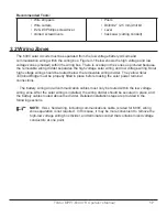
Page 11: ...tery current 48 volt DC systems Maximum 600 volt DC solar input voltage RS 232 EIA 485 MeterBusTM and Ethernet communication ports TS MPPT 60 600V 48 DB TR GFPD enhanced wiring Disconnect Box DB with...

Page 12: ...12 Getting Started 2 4 Features The features of the TS MPPT 600V TR GFPD models is shown in Figure 2 1 below An explanation of each feature follows Figure 2 1 TS MPPT 600V TR GFPD Features...

Page 13: ...position screw terminal for EIA 485 bus connections 9 Battery Breaker 63A rating pre wired Battery disconnect point 10 Battery Terminal Blocks and battery terminal connection points 11 Grounding Term...

Page 14: ...Breakers and leg ground fault interruption breakers 23 and Solar Breaker Post Connections pre wired underside Connection points for and solar wires 24 Solar Wiring Aperture Sensing opening for GFPD c...

Page 15: ...MeterBusTM network Meter Hub HUB 1 A Morningstar MeterBusTM network with multiple controllers requires a Meter Hub for electrical isolation The HUB 1 allows communication between MeterBusTM compatibl...

Page 16: ...ont et d truiront les circuits du TS MPPT 600V TR PRUDENCE Endommagement de l quipement Assurez une ventilation suffisante en cas d installation du TS MPPT 600V TR dans une enceinte L installation dan...

Page 17: ...ng Solar high voltage wiring should be routed below the removable wiring divider The yellow Solar Terminal Bridge must be properly fitted in place before making the solar power terminal connections Th...

Page 18: ...Wiring Positions TS MPPT 600V TR Figure 3 1 TS MPPT 600V TR GFPD high and low voltage wiring zones shaded areas 600V wiring below the removable Wiring Divider divider removed Low voltage wiring above...

Page 19: ...ock out types The TS MPPT 600V TR wiring box provides continuous and separate paths for high voltage solar and low voltage battery COM wiring routing These allow wiring to pass be tween TS MPPT 600V T...

Page 20: ...4 1 1 72 43 7 mm 1 36 34 5 mm Solar high voltage 4 11 1 2 or M20 7 8 22 2 mm Solar high voltage 5 1 1 2 or M20 7 8 22 2 mm Communication 6 1 3 4 1 09 27 8 mm Communication 7 4 3 4 Solar high voltage 8...

Page 21: ...exions d alimentation du TriStar MPPT 600V Use a 2 Phillips screw driver to remove the four 4 screws that secure the wiring box cover as shown in figure 3 4 below Figure 3 4 Remove the wiring box cove...

Page 22: ...r to Section 3 2 for detailed knockout information WARNING Shock Hazard Always use bushings connectors clamp connectors or wire glands in the knock out openings to protect wiring from sharp edges PRUD...

Page 23: ...as shown in figure 3 6 2 Place the TS MPPT 600V TR on a vertical surface protected from direct sun high temperatures and water The TS MPPT 600V TR requires at least 6 150 mm of clearance above and be...

Page 24: ...24 Installation Figure 3 6 Attaching the mounting hanger Figure 3 7 Allowing for passive cooling M6 Screw Mounting Hanger AT LEAST 1 25 mm AT LEAST 1 25 mm COOL AIR WARM AIR AT LEAST 6 150 mm...

Page 25: ...inez les c bles de r seau dans le m me conduit que les conducteurs d alimentation si tous les conducteurs sont valu s 600 V AVERTISSEMENT Risque de d charge lectrique Utilisez uniquement 300 volts ou...

Page 26: ...e RJ 45 Ethernet jack features two 2 indicator LEDs for connection status and network traffic Use CAT 5 or CAT 5e twisted pair cable and RJ 45 plugs If possible pull the network cable through conduit...

Page 27: ...EC requires that the wires carrying the system current never exceed 80 of the conduc tor s current rating Table 3 2 below provides the minimum size of copper wire for battery output connections allowe...

Page 28: ...28 Installation Figure 3 10 Power Connections TR Box Only...

Page 29: ...TR Operator s Manual To Grid tie Inverter Solar Input 48 Volt Battery Termination Solar Array Input Up to 2 Strings 4 A A B B C D D E E F F H H Grounding Block Grounding Block Figure 3 11 Power Conne...

Page 30: ...nduit with the high voltage solar conductors It is easier to pull the RTS and Sense wires before the power cables C Only route high voltage solar circuit conductors in the high voltage wiring zone and...

Page 31: ...TS MPPT 600V TR D connectez le coupe circuit interrupteur de la batterie avant le c blage sur le contr leur CONNECT WIRES TO AND BATTERY BANK POSTS not shown F Extend and connect the and battery wire...

Page 32: ...ure com pensated charging Connect the RTS to the 2 position terminal located between the pushbut ton and the LEDs see figure 2 1 The RTS is supplied with 33 ft 10 m of 22 AWG 0 34 mm2 cable There is n...

Page 33: ...volt age precisely with small gauge wires that carry very little current and thus have no voltage drop Both battery voltage sense wires are connected to the TriStar at the 2 position terminal located...

Page 34: ...Battery Type Absorp Stage Volts Float Stage Volts Equalize Stage Volts Equalize Interval Days off off off 1 Gel 56 00 54 80 off off on 2 Sealed 56 60 54 80 57 60 28 off on off 3 Sealed 57 20 54 80 58...

Page 35: ...on Choose between manual and automatic battery equalization charging In the manual equaliza tion setting an equalization will only occur when manually started with the pushbutton or when requested fro...

Page 36: ...ridged via EIA 485 REMARQUE Le r glage des param tres de r seau et des points de consignes personnalis s est toujours activ par les connexions RS 232 et EIA 485 Le contacteur de s curit Ethernet n act...

Page 37: ...on device GFPD The TS MPPT 600V TR GFPD affords this protection and installation is detailed in the GFPD 600V product manual In tradtional GFDI devices the system electrical negative should be bonded...

Page 38: ...une polarit invers e endommagera le TS MPPT 600V TR de fa on permanente Confirm that the solar and battery polarities are correct Note that a battery must be connected to the TS MPPT 600V TR to start...

Page 39: ...MPPT charge controller The two positions are illustrated in Figure 4 1 below Grid tie operation is engaged in the horizontal positions battery charging is enabled in the vertical pos tions In the eve...

Page 40: ...olar current flowing into the TS MPPT 600V TR and 50 amps of charge current flowing out to the battery Since power is the product of voltage and current Volts x Amps the following is true 1 Power Into...

Page 41: ...echarge the battery Absorption Stage When the battery has recharged to the Absorption voltage set point constant voltage regulation is used to maintain battery voltage at the Absorption set point This...

Page 42: ...properly ventilated CAUTION Equipment Damage Equalization increases the battery voltage to levels that may damage sensitive DC loads Verify all system loads are rated for the temperature compensated E...

Page 43: ...Some batteries such as the L 16 group will need more frequent equalizations The difference between the highest cell and lowest cell in a battery can also indicate the need for an equalization Either t...

Page 44: ...qualization should be set for manual only DIP switch 7 is Off After the equalization is finished add distilled water to each cell to replace gassing losses Check that the battery plates are covered Eq...

Page 45: ...Battery charging settings for each selectable battery type Shared Settings Value Units Absorption Extension Voltage 50 00 Volts Absorption Extension Time Absorption Time 30 minutes Float Exit Time ou...

Page 46: ...charging profile After entering Float stage the controller will only exit Float if the battery voltage remains below Float voltage for 60 cumulative minutes In figure 4 4 a system load turns on at 4...

Page 47: ...tage The diagram shows where Float stage would have occurred if Float was not cancelled Equalize Time Out 1 00 2 00 3 00 4 00 5 00 6 00 Absorp V Bulk Float Equalize Equalize timeout time hrs Equalize...

Page 48: ...carry no current the voltage at the TriStar will be identical to the battery voltage A 2 position terminal is used for the battery sense connection Generally accepted wiring practice is to limit volta...

Page 49: ...ery type selected see Section 4 2 Equalization will only occur if the selected battery type has an equalization stage Stop an equalization that is in progress This will be effective in either the manu...

Page 50: ...t is cleared General Transitions Controller start up G Y R one cycle Equalize request start G Y R G Y R G G Equalize cancelled G Y R G Y R R R Battery service is required all 3 LEDs blinking until ser...

Page 51: ...rk link and activity status as follows Condition Yellow LED Green LED Network Connection OK ON OFF Network Activity ON Blinking Error OFF ON GFPD 600V LED Indications and Audible Warnings A bi color L...

Page 52: ...ad The TS MPPT 600V TR will limit battery current to the Maximum Battery Current rating See Figure 9 1 Battery Current vs Array Voltage de rating graph in Section 9 0 An over sized solar array will no...

Page 53: ...the fault will automatically clear Custom Settings Edit R Y G sequencing A value has been modified in custom settings memory The controller will stop charging and indicate a fault condition After all...

Page 54: ...600V TR will limit battery charging current The array Voc should never exceed the 600 Volt maximum input voltage Charging Current Limit The array power exceeds the rating of the controller This alarm...

Page 55: ...ltiple communication ports can be used simultaneously For example a TS MPPT 600V TR may be connected to a MeterBusTM network for on site system metering connected to the internet for remote monitoring...

Page 56: ...M 2 600V are required not included A MeterBus Hub model HUB 1 is required for MeterBus networks containing multiple TS MPPT 600V TR controllers The ports on the hub are electrically isolated to preve...

Page 57: ...ata with MSViewTM PC software configure ethernet settings update controller firmware with MSLoadTM firmware utility NOTE The RS 232 and EIA 485 ports share hardware Both ports cannot be used simultane...

Page 58: ...ection between a TS MPPT 600V TR and a PC or other serial device Firmware updates can only be programmed through the RS 232 connection The serial connection is not typically used for multi controller...

Page 59: ...ns Power Data A Data B and Ground Data A B are differentially driven data lines that carry the network data Power and Ground connections provide power to the network The TS MPPT 600V TR does not suppl...

Page 60: ...ation Some of the many features the Ethernet connection pro vides include program custom settings with MSViewTM PC software monitor the controller from a web browser link up to four controllers for sy...

Page 61: ...ted on the serial label on the side of the unit for reference The controller s MAC Address is located on the serial label on the side of the controller Two 2 LEDs on the Ethernet jack indicate link an...

Page 62: ...r email and SMS alerts can be configured from the network settings web page in the MSView TriStar MPPT wizard View Logged Data The TS MPPT 600V TR logs up to 200 days of daily data The controller alwa...

Page 63: ...ations that require SNMP monitoring of deployed systems the TriStar MPPT will behave as an SNMP agent and supports the following commands TRAP GET GETNEXT A link to the agent Management Information Ba...

Page 64: ...occur Problem The TS MPPT 600V TR is not charging the battery Solution Check the three 3 battery SOC LEDs If they are flashing a sequence see Section 4 4 Faults Alarms of this manual to determine the...

Page 65: ...5 and RS 232 ports cannot be used simultaneously Only one port can be used at a time The RSC 1 adapter used to connect the PC to the EIA 485 network shows a green LED and pulses red when a connection...

Page 66: ...h the test button and then close the breaker to resume normal operation Have a qualified technician investigate the ground fault cause When a wiring error open breaker alarm has occurred correct wirin...

Page 67: ...er AVERTISSEMENT Indique une condition potentiellement dangereuse Faites preuve d une prudence extr me lors de la r alisation de cette t che PRUDENCE Indique une proc dure critique pour l utilisation...

Page 68: ...contact The TS MPPT 600V TR heatsink can become very hot during operation Use insulated tools when working with batteries Avoid wearing jewelry during installation The battery bank must be comprised o...

Page 69: ...ontez le TS MPPT 600V TR l int rieur Emp chez l exposition aux l ments et la p n tration d eau dans le contr leur Installer le TS MPPT 600V TR dans une situation qui emp che le contact occasionnel Le...

Page 70: ...autions CAUTION When replacing batteries use properly specified sizes types and ratings based on application and system design CAUTION Proper disposal of batteries is required Refer to local regulatio...

Page 71: ...aintenance Items 2 weeks after installation Re tighten power terminal connections to specified torque values 3 months after installation Re tighten power terminal connections to specified torque value...

Page 72: ...tions Damage by accident negligence abuse or improper use PV or load currents exceeding the ratings of the product Unauthorized product modification or attempted repair Damage occurring during shipmen...

Page 73: ...including LED indications C array configuration panel Pmax Voc Vmp Isc and battery voltage these specifications are needed to receive assistance D multi meter available for field troubleshooting 4 Af...

Page 74: ...roller Battery Charging Charging algorithm 4 stage Charging stages Bulk Absorption Float Equalize Temperature compensation coefficient 5 mV C cell 25 C ref Temperature compensation range RTS connected...

Page 75: ...HWD in 21 4 x 8 7 x 5 9 35 6 x 8 7 x 5 9 HWD cm 54 4 x 22 1 x 15 0 90 4 x 22 1 x 15 0 Product Weight lb kg 28 11 12 75 37 0 16 79 Wires Sizes all wire is assumed to be stranded unless noted otherwise...

Page 76: ...r 10 solid wire 8 AWG 40 in lb 4 52 N m 4 6 AWG 45 in lb 5 08 N m Grid tie Transfer Terminal Block Solar Input and Grid tie Output Screws 10 6 in lb 1 2 N m RTS and Battery Sense Terminal Screws 3 5 i...

Page 77: ...TriStar MPPT 600V TR Operator s Manual De ratings 60 0 200 425 525 600 Array Voltage Volts Battery Current Amps Battery Current vs Array Voltage OVER VO LTAGE Figure 9 1 Battery Current vs Array Volta...

Page 78: ...rrent Limit 60 Amp Battery Current Limit Vb 30 V 60 Amp Battery Current Limit Vb 20 V 60 Amp Battery Current Limit 60 Amp Battery Current Limit Vb 60 V 0 100 200 300 400 500 600 500 1000 1500 2000 250...

Page 79: ...wer Output W Power Output W Power Output W 300 Vmp 52 Vbatt 83 84 85 86 87 88 89 90 91 92 93 94 95 96 97 0 100 200 300 400 500 600 700 800 900 1000 1100 1200 1300 1400 1500 1600 1700 1800 1900 2000 21...

Page 80: ...with A1 and A3 Class B1 Safety EN60335 1 and EN60335 2 29 battery chargers UL1741 INVERTERS CONVERTERS AND CONTROLLERS AND INTERCONNECTION SYSTEM EQUIPMENT FOR USE WITH DISTRIBUTED ENERGY SOURCES FIRS...

Page 81: ...45 Amps 40 Amps 35 Amps 30 Amps 25 Amps 20 Amps 15 Amps 00 89 6 97 8 107 5 119 5 134 4 153 6 179 2 215 1 268 9 358 5 0 71 0 77 5 85 2 94 7 106 6 121 8 142 1 170 5 213 1 284 2 2 44 7 48 7 53 6 59 6 67...

Page 82: ...ize mm2 60 Amps 55 Amps 50 Amps 45 Amps 40 Amps 35 Amps 30 Amps 25 Amps 20 Amps 15 Amps 70 33 9 37 0 40 7 45 2 50 8 58 1 67 8 81 4 101 7 135 6 50 26 9 29 3 32 3 35 8 40 3 46 1 53 8 64 5 80 6 107 5 35...

Page 83: ...Wire Size mm2 60 Amps 55 Amps 50 Amps 45 Amps 40 Amps 35 Amps 30 Amps 25 Amps 20 Amps 15 Amps 70 27 3 29 8 32 8 36 4 41 0 46 8 54 6 65 6 82 0 109 3 50 21 7 23 6 26 0 28 9 32 5 37 1 43 3 52 0 65 0 86...

Page 84: ...ize mm2 60 Amps 55 Amps 50 Amps 45 Amps 40 Amps 35 Amps 30 Amps 25 Amps 20 Amps 15 Amps 70 33 9 37 0 40 7 45 2 50 8 58 1 67 8 81 4 101 7 135 6 50 26 9 29 3 32 3 35 8 40 3 46 1 53 8 64 5 80 6 107 5 35...

Page 85: ...UTHOR BE LIABLE FOR ANY DIRECT INDIRECT INCIDENTAL SPECIAL EXEMPLARY OR CONSEQUENTIAL DAM AGES INCLUDING BUT NOT LIMITED TO PROCUREMENT OF SUBSTITUTE GOODS OR SERVICES LOSS OF USE DATA OR PROFITS OR B...

Reviews: