STEP 2:
The ladder should be installed underneath the escape window of the 5th wheel. The preferred location is for
the platform to be centered underneath the window. However, The MOR/safe Escape Ladder frame mount
MUST
be mounted into the main upper deck tube structure (usually 2” x 6”) using the four toggle nuts and bolts provided in
the installation hardware kit. It’s important to properly locate the main upper deck tubes underneath the exterior skin
of the 5th wheel for installation of the ladder frame mount. This may position the ladder so that it it is offset from the
center of the window.
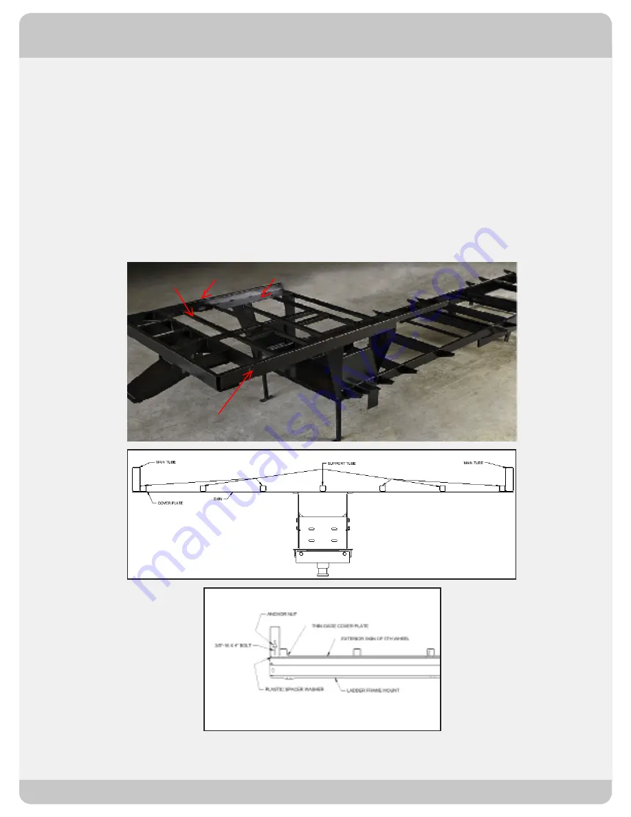
The picture and drawing below are representative of the steel structural frame in the upper deck of a 5th wheel*(Fig.
1 and 2). It’s common for manufacturers to add smaller support tubes next to the main tube structure and also to cover
the tubes with a thin gage steel cover plate. The smaller tube structure, (usually 1” x 1”) and thin gage cover plates
will not provide adequate support for the ladder frame mount primary toggle nuts and bolts. The smaller tubes are
adequate for the Tek screws that are used as secondary mounts to help secure the ladder frame mount to the upper
deck of the 5th wheel. Figure 3 shows a proper location for the toggle nut and bolt used to secure the ladder to the
ladder frame mount.
In order to reveal the location of the cross members, it is recommended that a section of the exterior skin of the 5th
wheel is removed. The next step (Step 3) may be skipped only if the exact location of the cross members is known.
INSTALLATION INSTRUCTIONS
SP56-137 STANDARD PLATFORM LADDER
* The smaller support tubes or steel plate referenced in this picture may be in a different location and/or in some cases may not exist on your 5th wheel.
What is most important is that the MOR/safe Escape Ladder Frame Mount is installed into the main upper deck tube structure (usually 2” x 6” tube) using
the 4 toggle nuts and bolts provided in your installation hardware kit, one in each corner as detailed in the steps that follow.
2
Fig. 1
Fig. 2
Fig. 3
Main Upper Deck
Tube - Curb Side
Thin Gage Cover Plate
Support Tube
Main Upper Deck
Tube - Road Side


