background image

The Specialist In Drum Handling Equipment

Model 515-N-115

Vertical-Lift Drum Pourer, Scale-Equipped,  

60”, DC Power Lift and Tilt

Operator’s Manual for Morse Model 515-N-115

with Serial Number 249855 to ______

morsedrum.com

Copyright 2022  -  Morse Mfg. Co., Inc. 


Form OM515-115 (249855-______) 

(Updated 23 Feb, 2022) 

4

Controls

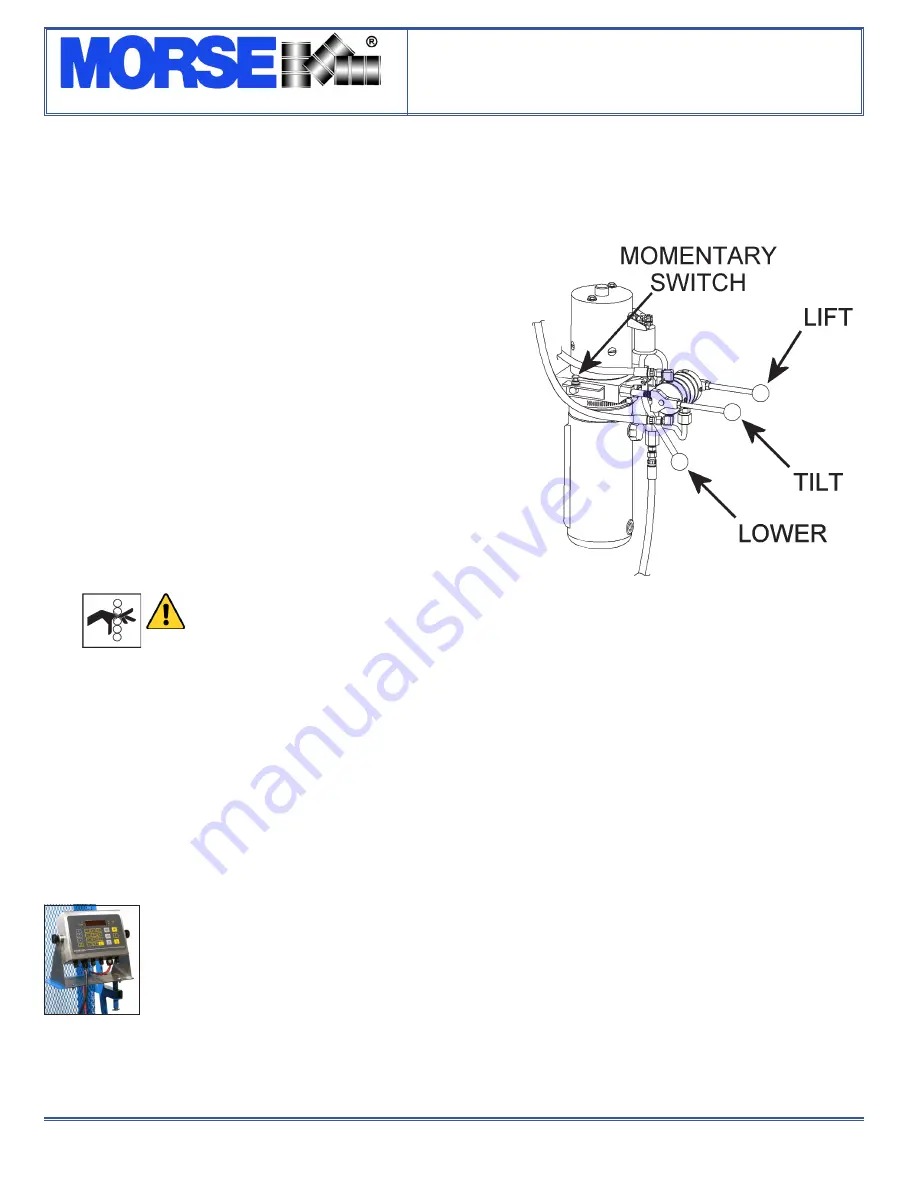
The Morse Vertical-Lift Drum Pourer is manually propelled and 

steered. The drum lift and tilt controls are powered by a 12V DC 

motor with a momentary switch. There are two functions for the 

operator to control (Figure 3.1):

1.  LIFT and Lower Function for vertical positioning of the drum 

To raise the drum 

Turn the motor on by holding the momentary switch in the on position. 

With the motor on, raise the LIFT handle.  


To lower the drum 

With the motor off, push in the LOWER handle.


2.  TILT Function to control the degree of rotation of the drum 

To tilt the drum forward for pouring 

Turn on the motor by holding momentary switch in the on position. 

With the motor on, raise the tilt handle. 


To return the drum to vertical position 

Turn on the motor by holding momentary switch in the on position. 

Push the tilt handle down.

WARNING

 - Watch out for pinch points


 Stay clear of moving parts. Operator should 

remain behind the push handle during the lift 

operation.

Floor Lock

Floor lock handle is located on left side of push handle.  Pulling floor lock handle toward operator until it locks in down position activates 

the floor lock. When floor lock is activated it prevents unwanted free wheeling of unit.  Floor conditions determine effectiveness of floor 

lock.  Operator should verify its holding action before depending on it to hold.

Drum Holder Assembly

MORCINCH

TM

 Drum Holder assembly (“saddle”) is the component on Vertical-Lift Drum Pourer intended to hold drum.  Carriage assembly 

moves vertically along mast to position drum holder assembly at correct height to secure drum around it’s middle using cinch chain and 

ratchet tightening system.  

The MORCINCH

TM

 Drum Holder accepts accessories to handle plastic drum, fiber drum, or a smaller diameter drum.

Scale

The scale is simple to use and to read enabling accurate batching by weight.  The touch pads include numbers for 

tare entry.  Four load cells accurately sense the weight regardless of the tilt angle of the drum. Battery saving “sleep” 

mode turns indicator off when scale is not in use.

N-Type Scale

Economical general purpose instrument for use in a variety of weighing applications. NOT for use in hazardous areas. 

Powered by five ordinary alkaline D-cell batteries.

“N” Type scale 

indicator NOT 

for hazardous 

environments.

Figure 3.1

Summary of Contents for 515-N-115

Page 1: ...ke a loop to lift by Attach loop to an overhead crane and raise slowly Limited 2 Year Warranty Morse drum handling equipment is guaranteed against defects in workmanship or materials for two years when used properly within its rated capacity Warranty does not cover wear from normal use or damage from accident or abuse Motors and other purchased parts carry the warranties of their manufacturers For...

Page 2: ...the unit Under no circumstances should any modifications be made to the Morse machinery without factory authorization Any modifications may void the warranty This machine was designed to perform a specific job and alterations may result in injury to operator or machine WARNING No loose fitting clothing Wear close fitting clothing and safety equipment appropriate to the job Loose fitting clothing m...

Page 3: ...er drum insert the correct size Diameter Adapter into the standard drum holder See Diameter Adapter info at https morsedrum com products diameter adapters ONLY Diameter Adapters for drum with 17 5 44 5 cm diameter or smaller have integrated brackets to prevent drum slipping length ways NOTE For 30 gallon 114 Liter PLASTIC drum insert Diameter Adapter AND install Bracket or Top Rim Clamp to prevent...

Page 4: ...Operator should remain behind the push handle during the lift operation Floor Lock Floor lock handle is located on left side of push handle Pulling floor lock handle toward operator until it locks in down position activates the floor lock When floor lock is activated it prevents unwanted free wheeling of unit Floor conditions determine effectiveness of floor lock Operator should verify its holding...

Page 5: ...m to impact on floor pouring station etc or spill or damage could occur CAUTION Do NOT transport with drum raised ALWAYS LOWER THE DRUM HOLDER TO LOWEST POSITION BEFORE TRANSPORTING Unit can become unstable when transporting with raised load 5 Lift drum to desired pouring height Operate tilt control as described in Machine Description Controls to adjust drum attitude Floor lock should be engaged w...

Page 6: ...djust or replace parts as necessary to prevent failure and maintain proper function 3 Inspect the hydraulic system for oil drips hose damage or other signs of wear Inspect the level of the hydraulic fluid Replace any parts that show signs of wear 4 Grease wheel bearings periodically Oil or grease all moving parts including the gears and sprockets in the tilt drive and the ratchet and pawl 5 Worn o...

Reviews: