The Specialist In Drum Handling Equipment
Model 405-114
Omni-Lift Karrier
Operator’s Manual for Morse Omni-Lift Karrier Model 405-114
Serial Number 0617 to ____ (MMYY)
morsedrum.com
Copyright 2019 - Morse Mfg. Co., Inc.
Form OM405-114 (0617-____)
(Updated June 12, 2019 3:30 PM)
3
Important
Review the Material Safety Data Sheet(s) for the material(s) in the drum(s) and take all necessary precautions. Safety shoes, work
1.
gloves, hard hat and other personal protective devices are recommended.
Please read all instructions thoroughly before attempting to operate your new Morse drum handler.
2.
The Omni-Lift Karrier has a maximum capacity rating of 800 Lb. (363 kg) full drum and 500 Lb. (227 kg) half-full drum and is
3.
designed to lift, move and pour a 55-gallon (210 liter) steel drum. DO NOT exceed these ratings. Exceeding these ratings or handling
drums other than those mentioned above is unsafe and could result in equipment damage, excessive wear or awkward handling.
Omni-Lift Karrier are intended for lifting, moving, and holding drums for tilting, pouring or racking. Drums may be lifted upright to or
4.
from the floor or other suitable surface on dollies, scales, etc.
When loading, unloading, operating, or maintaining your Morse drum handler, always use care and good judgment. Maintain secure
5.
footing and a firm hold. Keep hands and loose clothing away from all moving parts. Never allow anyone to be below any part of a
raised drum handler or drum. Read operating instructions and review the pictures in the sales brochure before operation.
Prior to initial use, inspect all moving parts and test rotation of drum holder assembly. Inspect drum holder assembly for proper
6.
operation. Perform necessary load test, inspections, operator training, etc.
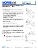
Figure 3.0
Controls
The Morse Omni-Lift Karrier is manually propelled and steered.
The hydraulic pump is powered by a vane type air motor. The air motor is control
by a momentary air valve located on the air motor. Attach air supply to the air valve.
There are two functions for the operator to control (Figure 3.0):
1. LIFT and lower function for vertical positioning of the drum.
To raise the drum, hold the air valve handle in the on position and raise the
•
LIFT handle. Release the two valve handles when desired drum height is
reached.
To lower the drum, push in the LOWER handle. Air motor is not needed.
•
2. TILT function to control the degree of rotation of the drum.
To tilt the drum forward for pouring, hold the air valve handle in the on position
•
and raise the TILT handle. Release the two valve handles when drum angle is
reached.
To return the drum to vertical position, hold the air valve handle in the on
•
position and push down on the TILT handle.
Floor Lock
The screw-down floor lock is located on the base of the tower (figure 3.1). Turning the floor lock clockwise until it locks in the down posi
-
tion activates the floor lock. When the floor lock is activated it prevents unwanted free wheeling of the unit. Floor conditions determine
the effectiveness of the floor lock. The operator should verify its holding action before depending on it to hold.


