background image

The Specialist In Drum Handling Equipment

Model 83


Pail Handler

operator’s Manual for Morse Model 83

serial number 0819 to ____ (MMYY)

morsedrum.com

Copyright 2020  -  Morse Mfg. Co., Inc. 


Form PL83 (0819-____)   

(Updated 3 Jun, 2020)


6

operating Instructions

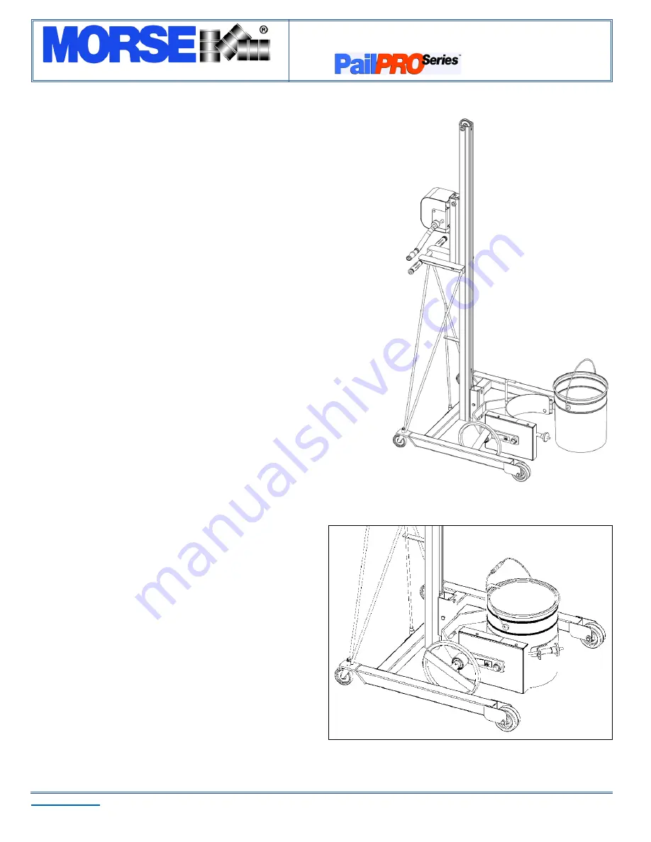
1.  Push the Pail Handler to the pail.

2.  Using the cable winch, crank the handle to position the pail holder assembly 

with the back band at the middle of the pail. (see Figure 1).  If the pail has a 

pivoting wire handle, swing it to lay on the front side to clear the back band.  

With the front band hinge plate and clamp screw knob swung open, push 

the unit forward until the back band rests firmly against the pail.  Engage the 

screw down floor lock.

3. 

Attaching the pail: 

First, swing pivoting wire handle to lay on the back band 

side of the saddle.  Next, close the front band hinge plate tightly against the 

pail (see Figure 2).  Swing the clamp screw knob and engage the threaded 

rod into the slot on the front band hinge plate as shown in Figure 2.  Tighten 

the clamp screw knob to secure the pail into the saddle.

4. Crank the cable winch to lift pail clear of floor.  Disengage floor lock.  Roll to 

dispensing location.

5. Crank cable winch to raise pail to desired pouring height.  Engage the screw-

down floor lock.  Tilt the pail forward until desired pouring angle.  The pail will 

remain in this position.  

6. When dispensing is complete, tilt pail back to upright position.  Disengage the 

floor lock and lower the pail to transporting height; about 6” off the floor.

7. Push the unit to the pail storage area and lower to the floor.  Engage the floor 

lock. Loosen the clamp screw knob until it can be released from the slot in the 

front band hinge plate.  Roll Pail Handler away from pail.


Maintenance

Periodic inspection for the general condition of structural and 

mechanical components is imperative for safe and efficient 

operation.

Periodically inspect all moving parts, framework, and contact areas 

for signs of wear, fatigue, or loosening.  Tighten, adjust, or replace 

parts as necessary to prevent failure and maintain proper function.

Periodically lubricate vertical track rollers, casters, wheels, saddle 

shafts, and cable pulleys and/or shafts.

Figure 1

Figure 2

Summary of Contents for PailPro 83

Page 1: ...orkmanship or materials for two years when used properly within its rated capacity Warranty does not cover wear from normal use or damage from accident or abuse Motors and other purchased parts carry the warranties of their manufacturers For warranty claims contact your Morse Dealer to obtain a return authorization number and for return freight advice Return freight must be prepaid In all instance...

Page 2: ... the Unit Under no circumstances should any modifications be made to the Morse machinery without factory authorization Any modifications may void the warranty This machine was designed to perform a specific job and alterations may result in injury to operator or machine WARNING No Loose Fitting Clothing Wear close fitting clothing and safety equipment appropriate to the job Loose fitting clothing ...

Page 3: ...ht if counterweight option is used Options and Accessories Counterweight Kit Option Kit 3930 P The optional counter weight kit Part 3930 P allows the Model 83 to be configured as an extended reach dispensing unit Easily converted this option provides over one foot of reach beyond the front casters The capacity is reduced to 75 Lb 34 kg with the optional counterweight kit Model 83 shown with option...

Page 4: ...re A Figure B B Locate the floor lock crank weldment item 25 Feed the crank handle up through the guide on the mast until the two holes in the floor lock angle line up with the two holes in the base tube Bolt in place using the two 3 8 16 x 3 bolts item 10 Do not install nuts at this point C Align the two holes at the bottom of the mast channel with the two bolts installed in step B above Secure t...

Page 5: ...lley tube on the carriage weldment and centered on the bolt hole insert one 3 8 16 x 2 1 4 bolt item 26 and secure with 3 8 lock nut item 27 B Ensure that the cable travels over the two pulleys correctly and that the cable end is securely fastened to the carriage assembly The crank handle from the winch has been removed for 5 shipping Install the hand crank by removing the bolt washer spacer and s...

Page 6: ...ten the clamp screw knob to secure the pail into the saddle 4 Crank the cable winch to lift pail clear of floor Disengage floor lock Roll to dispensing location 5 Crank cable winch to raise pail to desired pouring height Engage the screw down floor lock Tilt the pail forward until desired pouring angle The pail will remain in this position 6 When dispensing is complete tilt pail back to upright po...

Page 7: ...AVE MID 1 1 2 STEEL 83 8 2 3803 P SHAFT PULLEY 83 9 1 3798 P TOP SHEAVE 3 POLY 83 PP 10 3 193 P SCREW TEK 12 14 X 3 4 3 PT 11 1 4355 P MAST WELD 83 12 1 4329 P CARRIAGE ASM 83 13 4 1315 P HHCS 3 8 16 X 2 3 4 GR2 14 2 3921 P NUT 3 8 16 ACORN 15 2 3885 P WHEEL 4 X 1 1 2 83 16 2 3789 P CASTER 3 SWIVEL STEM 83 17 1 3790 P BASE WELD 83 19 2 136 P GRIP HANDLE 7 8 X 4 3 4 20 1 4381 P HHCS 3 8 16 X 3 1 2 ...

Page 8: ...38 1 4161 P PLATE IDLER BOLT ON 83 39 2 64 P ROLL PIN 3 16 X 1 1 4 40 1 55 P WASHER 3 4 SAE FL 1 1 2 OD 41 2 3804 P SHCS 1 4 20 X 3 1 4 43 1 5441 P KNOB CLAMP SCREW ALUMINUM 44 1 3795 P WELD FRONT BAND 83 Carriage Assembly Part 4329 P ITEM QTY PART DESCRIPTION 45 1 4221 P CLAMP SCREW WELD 83 46 1 3796 P SADDLE ASM 83 47 1 6068 P COVER GEAR OUTSIDE 83 48 4 193 P SCREW TEK 12 14 X 3 4 3 PT 49 1 2537...

Reviews: