background image

www.morsona.com

[ 30 ]

[ 31 ]

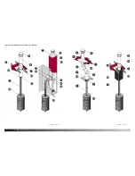
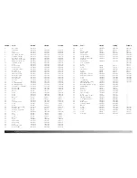
pOS.Nr.:  parts: 

7642 NA 

7644 NA 

7648 NA


Base plate 

447601xx 

--- 

---

Top frame 

447607xx 

447607xx 

447607xx

3 Door 

447603xx 

447603xx 

447603xx

Front frame 

447656xx 

447656xx 

447656xx

Rear plate, outside 

447610xx 

447610xx 

447610xx

Top plate, outside 

447611xx 

447611xx 

447611xx

Rear plate, inside 

44760400 

44760400 

44760400

Side plate, inside, right 

447657xx 

447657xx 

447657xx

Side plate, inside, left 

447630xx 

447630xx 

447630xx

10 

Top plate, inside 

447605xx 

447605xx 

447605xx

11 Glass 

79760100 

79760100 

79760100

12 

Air Canal, top 

44761500 

44761500 

44761500

13 

Air Canal, rear 

44765400 

44765400 

44765400

14 

Intermediate plate 

34761200 

34761200 

34761200

15 

Brick, back 

79760700 

79760700 

79760700

16 

Air Canal, front 

447613xx 

447613xx 

447613xx

17 

Side plate, outside 

447609xx 

447609xx 

447609xx

18 

Brick, side, right 

79760300 

79760300 

79760300

19 

Brick, side, left 

79760400 

79760400 

79760400

20 

Ash tray, front 

447617xx 

447617xx 

447617xx

21 

Ash tray 

71760400 

71760400 

71760400

22 Screw 

73861800 

73861800 

73861800

23 

Secondary Damper 

71760100 

71760100 

71760100

24 

Secondary Handle 

71760200 

71760200 

71760200

25 

Close plate, sec. Damper 

71760300 

71760300 

71760300

26 

Distance tube 

71810200 

71810200 

71810200

27 

Distance tube 

71810300 

71810300 

71810300

28 Washer 

736106 

736106 

736106

29 Screw 

74162000 

74162000 

74162000

30 Screw 

73851100 

73851100 

73851100

31 Screw 

73861300 

73861300 

73861300

32 Washer 

791891 

791891 

791891

33 Screw 

731620 

731620 

731620

34 Cover 

448120xx 

448120xx 

448120xx

35 

Fitting for Cover 

71813200 

71813200 

71813200

36 Screw 

731608 

731608 

731608

37 Screw 

731635 

731635 

731635

38 

Rondelle, rear, outside 

71762100 

71762100 

71762100

39 

Distance tube 

541439 

541439 

541439

40 

Rondelle, rear, inside 

542633 

542633 

542633

41 Screw 

73861400 

73861400 

73861400

42 Nut 

735006 

735006 

735006

43 Screw 

791835 

791835 

791835

44 Screw 

731625 

731625 

731625

45 Washer 

736210 

736210 

736210

46 Screw 

73850800 

73850800 

73850800

47 

Glass fitting 

71611361 

1611361 

1611361

48 

Glass fitting 

54181361 

54181361 

54181361

49 Screw 

73861000 

73861000 

73861000

50 

Baffle plate, top 

71761700 

71761700 

71761700

52 

Distance tube 

54143700 

54143700 

54143700

pOS.Nr.:  parts: 

7642 NA 

7644 NA 

7648 NA


53 Cover 

442610xx 

442610xx 

442610xx

54 Bar 

545006 

545006 

545006

55 

Distance tube 

545007 

545007 

545007

56 

Plug f. Door 

71760700 

71760700 

71760700

57 

Fittig f. Door 

71760600 

71760600 

71760600

58 

Fitting f. Handle 

71761100 

71761100 

71761100

59 

Fitting for Flue Collar 

44256700 

44256700 

44256700

60 Pedestal 

--- 

--- 

547605xx

61 

Fittig f. Door 

71762400 

71762400 

71762400

62 

Foot, f. Pedestal 

--- 

--- 

447616xx

63 Screw 

--- 

--- 

731616

66 Washer 

746006 

746006 

746006

67 Screw 

739625 

739625 

739625

68 

Flue Collar 

443441xx 

443441xx 

443441xx

69 Screw 

743625 

743625 

743625

70 

Stop Bar 

544541 

544541 

544541

71 

Baffle plate, cast iron 

34762700 

34762700 

34762700

72 

Baffle plate, stainless 

71762200 

71762200 

71762200

73 Screw 

74163504 

74163504 

74163504

74 Screw 

74160804 

74160804 

74160804

75 

Jet, pilot air 

71762300 

71762300 

71762300

76 

Tightening tape, f. glass 

79074200 

79074200 

79074200

83 

Door bottum part 

447624xx 

447624xx 

---

84 

Base plate, bottom section  

447629xx 

447628xx 

---

85 

Rubber Stop 

79082007 

79082007 

---

86 Screw 

742612 

742612 

---

87 

Ball track 

79082006 

79082006 

---

88 

Pop rivet  

74700300 

74700300 

---

89 

Plate f. Drawer 

71760900 

71760900 

---

90 Screw 

731612 

731612 

---

91 

Distance plate, Drawer 

71761000 

71761000 

---

92 

Side plate, bottom 

447623xx 

447623xx 

---

93 

Rear plate, bottom 

447625xx 

447625xx 

---

94 Screw 

73860800 

73860800 

---

95 

Drawer Box 

71760800 

71760800 

---

96 

Top plate, bottom 

44762200 

44762200 

---

97 Washer 

79189800 

79189800 

---

98 Screw 

73961000 

73961000 

73961000

99 Handle 

71762600 

71762600 

71762600

100 Screw 

73860900 

73860900 

73860900

101 Screw 

739406 

739406 

739406

102 

Front Grate 

54762721 

54762721 

54762721

Summary of Contents for 7642

Page 1: ... 1 7600 I nstallation operating instructions for USA Canada Read the entire manual before installing and using your Morsø stove A French version of the manual can be downloaded at www morsona com ...

Page 2: ...known for her pioneering designs which all take their starting point in her unique universes and totally special organic language of form and lines Thus the Morsø 7600 was also created in this way it is completely unique with its circular form round feminine transitions and its huge glass window the biggest in Morsø s history of stoves Morsø 7642 Morsø 7648 Morsø 7644 Technical Specifications Maxi...

Page 3: ... United States and ULC S627 for Canada The heater is listed for burning wood only Do not burn other fuels Under specific test conditions this heater has been shown to delivery heat at rates ranging from 10 875 to 21 267 Btu hr Always check Local Building Codes When installing or operating your Morsø heater always follows the instructions detailed within this manual Please store in a safe place and...

Page 4: ...roperly sized to the immediate area you need to heat An under sized heater may not deliver the required heat output without overheating and an oversized heat may produce too much heat Always use approved chimney and chimney lining materials Your chimney should be inspected and swept by an approved chimney sweep at least once every year dependent upon usage Installation Preparation We recommend ins...

Page 5: ...www morsona com 8 9 Typical Factory Built or Masonry Chimney Installations See page 10 for key See page 10 for key ...

Page 6: ...ate component parts for your instal lation DVL DuraBlack Chimney Adapter must be used when connecting DVL pipe to a Ceiling Support Box or Finishing Collar When connecting DuraBlack pipe a DVL DuraBlack Chimney Adapter DuraBlack Slip Connector or Snap Lock Adapter must be used Wall Thimble must be installed with an appropriate length of chimney pipe for all horizontal through the wall installation...

Page 7: ...ther than sharp angles where a change of direction is required All parts of the venting must be accessible for cleaning purposes In horizontal runs of chimney maintain a distance no less than18 inches from the ceiling Keep it as short and direct as possible with no more than two 90 degree turns Slope horizontal runs of connector upward 1 4 inch per foot 20 mm per metre going from the stove toward ...

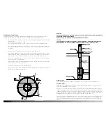
Page 8: ...ide 6 8 200 mm C Extending distance left side 6 8 200 mm D Extending distance front 16 18 450 mm US FLOOR PROTECTOR MUST BE NON COMBUSTIBLE MATERIAL IT MUST EXTEND FRONT SIDE REAR AS INDICATED CANADA FLOOR PROTECTOR MUST BE NON COMBUSTIBLE MATERIAL IT MUST EXTEND FRONT SIDE REAR AS INDICATED MAXIMUM ALCOVE DEPTH 32 813 MM Clearance Requrements alcove installation using double wall connector USA Ca...

Page 9: ...ation of file Scale Format Released Construction Date Borefixturer 7600 16 a Page 3 WARNING NEVER DRAW COMBUSTION AIR FROM A WALL FLOOR OR CEILING CAVITY OR FROM ANY ENCLOSED SPACE SUCH AS AN ATTIC OR GARAGE DO NOT INSTALL IN A BEDROOM OR A ROOM WHERE PEOPLE SLEEP CAUTION THE STRUCTURAL INTEGRITY OF THE MOBILE HOME FLOOR WALL AND CEILING ROOF MUST BE MAINTAINED I E DO NOT CUT THROUGH FLOOR JOIST W...

Page 10: ...ted with chemicals should also be avoided Starting the first fire When lighting your heater for the first time or after dormant periods the initial fire should be fairly gentle so that the finish paint can cure and the main cast plates of the heater can expand gently and settle into position The heater paint cures at higher temperatures and it should be expected that during the initial firing proc...

Page 11: ...h scraper to spread the embers but ensure that most of them are positioneded at the front of the stove 8 Re Fuelling Place three pieces of wood of approx lb each and approx 9 8 long over the embers in a single layer with a distance of approx between each piece When the air controls are opened fully and the door is closed the wood will ignite within 2 3 minutes 9 Optimal combustion Finally adjust t...

Page 12: ...ly important to maintain a good layer of glowing embers throughout the combustion process Low heat output less wood less air High heat output more wood more air Soot particles will accumulate on the glass and vermiculite bricks if the heater is operated too low or if your wood is not well seasoned Maintenance A clean well maintained heater is essential for good health and a safe home environment Y...

Page 13: ...t once every year preferably in the summer to ensure that other blockages such as birds nest have not occurred Ash disposal The level of ash removal is dependent upon the level of use the type of wood burned and the strength of chimney draft A 1 ash bed should be maintained during general and excess ash should be removed when necessary Where the heater is equipped with an ash pan excess ash should...

Page 14: ...ce a chimney fire you must act promptly 1 Completely close the primary air control 2 Ensure ALL persons have vacated the building 3 CALL THE FIRE DEPARTMENT Annual maintenance Prior to every heating season you should thoroughly clean and inspect the entire installation repairing any damage and replace any parts that show signs of wear tear Thoroughly clean and inspect the chimney and chimney conne...

Page 15: ... stang til håndtag RSV 28 05 2009 h Tilføjet pinolskrue pos 101 RSV 11 02 2010 i Tilføjet forrist pos 115 RSV 05 05 2010 j Ændret pos forrist fra 115 til 102 RSV 16 12 2010 32 60 62 32 63 33 5 78 81 41 63 80 79 32 1 7 32 32 41 32 78 63 32 32 32 32 77 82 92 95 94 32 88 93 91 84 89 90 85 86 87 83 44 32 32 92 44 32 44 87 88 32 44 94 44 32 44 44 32 96 97 94 84 Revisions Rev Sign Title Drawing no 1 7 R...

Page 16: ...400 73861400 42 Nut 735006 735006 735006 43 Screw 791835 791835 791835 44 Screw 731625 731625 731625 45 Washer 736210 736210 736210 46 Screw 73850800 73850800 73850800 47 Glass fitting 71611361 1611361 1611361 48 Glass fitting 54181361 54181361 54181361 49 Screw 73861000 73861000 73861000 50 Baffle plate top 71761700 71761700 71761700 52 Distance tube 54143700 54143700 54143700 POS NR Parts 7642 N...

Page 17: ...www morsona com 32 Morsø Jernstøberi A S 19 08 2013 72761500 ...

Reviews: