MORTEX
PRODUCTS
INC
FORT
WORTH,
TX
76106
Page
11
SECTION V: TROUBLE SHOOTING
The following checks should be made before trouble shooting
the furnace controls for a no heat issue.
1.
Check all of the circuit breakers. Make sure they are
turned to the “ON” position and have not tripped.
2.
Check all fuses, especially the 3 amp fuse on the top right
side of the control box. If the fuse is blown, check the
wiring with an OHM meter for a short to ground. If
shorted, repair the short, and then replace the fuse.
3.
Check any electrical switches that are external to the
furnace to make sure they are turned on.
4.
Check all wiring connections, especially on any of the
components, to ensure they are securely fastened.
If you have 240 VAC coming out of the control box circuit
breakers and you have 24 VAC between the load side if the 3
amp fuse and ground, then continue on through the rest of the
checks.
X-13 Motor Check – Heating Mode
1.
If the motor is not running, check for 240 VAC and 24
VAC at the motor terminals. If the 240 VAC and 24 VAC
is present at the motor terminals but the motor is not
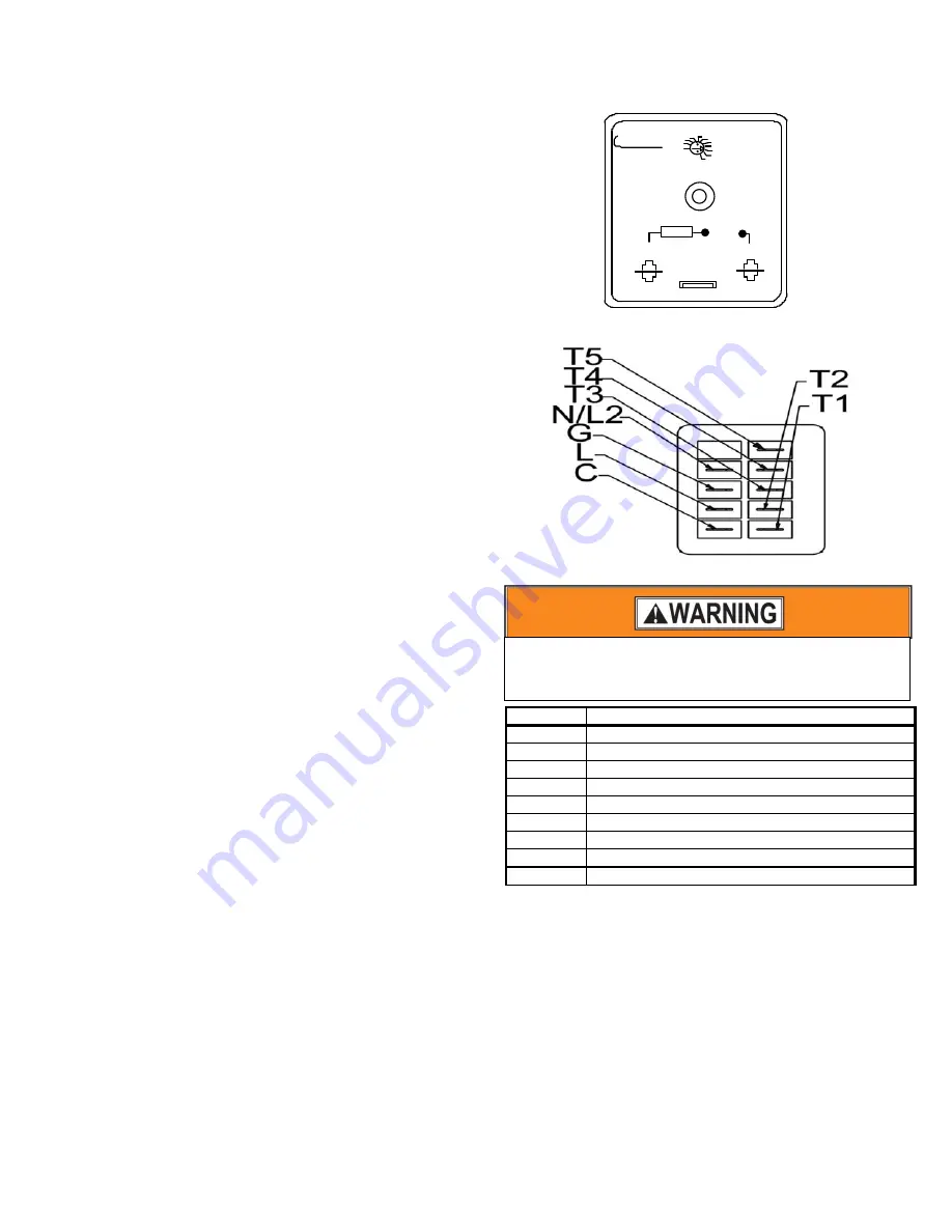
operating, then replace the motor. Refer to Figure 12 and
Table 1 for terminal locations and definitions.
A.
If 240 VAC is not present at the motor check for a
broken wire between the circuit breaker and the
motor.
B.
If 240 VAC is present at the motor terminals continue
to the next check.
2.
If 24 VAC is not present at the motor check for 24 VAC
across the heater relay coil.
A.
If 24 VAC is present at the heater relay coil, the wire
going to the motor is bad and needs to be replaced.
B.
If 24 VAC is not present at the heater relay coil check
the thermostat “W” circuit wire connections and the
thermostat.
X-13 Motor Check – Cooling Mode
1.
If the motor is not running, check for 240 VAC and 24
VAC at the motor terminals.
A.
If the 240 VAC and 24 VAC is present at the motor
terminals but the motor is not operating, then replace
the motor. Refer to Figure 12 and Table 1 for
terminal locations and definitions.
B.
If 240 VAC is not present at the motor check for a
broken wire between the circuit breaker number one
and the motor.
C.
If 240 VAC is present at the motor terminals continue
to the next check.
2.
If 24 VAC is not present at the motor speed tap terminals;
check for 24 VAC at terminal #1 on the TDR
A.
If 24 VAC is present at terminal #1, the wire going
to the motor is bad and needs to be replaced.
B.
If 24 VAC is not present at terminal #1 check
terminal #3.
C.
If 24 VAC is present at the terminal #3 replace the
TDR.
1
3
LOAD
1.5 AMP
MAX
CUT WIRE FOR 120/240 VAC
.4
15
30 SECONDS
MADE IN
THE USA
ICM
HMPS00C2X30
DELAY ON
MAKE
TIMER
CONTROLS
INPUT
19-240
VAC
Figure 11: Time Delay Relay (TDR) Terminals
Figure 12: X-13 Motor Terminals
Terminal
Connection
C
Speed
Tap
Common
‐
24
VAC
Common
L
Supply
Voltage
to
Motor
‐
240
VAC
Line
1
G
Ground
Connection
N
Supply
Voltage
to
Motor
‐
240
VAC
Line
2
1
Low
Speed
Tap
‐
24
VAC
2
Med
‐
Low
Speed
Tap
‐
24
VAC
3
Medium
Speed
Tap
‐
24
VAC
4
Med
‐
High
Speed
Tap
‐
24
VAC
5
High
Speed
Tap
‐
24
VAC
Table 1: X-13 Motor Terminal Connections
Heater Element Is Not On
Check for 240 VAC between each of the heater elements. If
240 VAC is present, check the current draw on each heater. If
there is 200 – 250 VAC across the heaters but a heater is not
drawing the proper current or is showing almost no current
draw check the limit for that heater. If the limit is good but
there still is no current flow then, check to see if the heater is
defective.
The heater amps are as follows:
4 kW Heater = 16.7 amps
5 kW Heater = 20.8 amps
6 kW Heater = 25.0 amps
The heater design is as follows:
To avoid personal injury or property damage, make certain
that the motor leads cannot come into contact with non-
insulated metal components of the unit.


