USE
WELDING DIGITAL CONTROL
M
33.
3
© MOSA
REV.1-01/08
WIRE FEEDER CONNECTED WITH REMOTE
CONTROL CONNECTOR
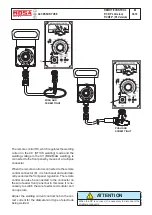
Wire feeder connection
Connect the wire feeder to the welder with the
welder turned off:
-Welding cable between the machine’s (9) welding
plug (+) and the wire feeder.
-Welding cable between the machine’s (10) welding
plug (-) and the piece to be welded.
-Control/power cable between the machine’s
connector (X1) and the corresponding connector
on the wire feeder.
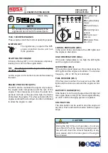
Start the machine welder
The “ON” LED will be off and will turn on only when
there is voltage at the welding plugs (and therefore
at the wire).
The voltage is only present when the welding torch
button is pressed.
The setting of the welding voltage is done using the
knob on the wire feeder.
The adjusting knob on the welder is automatically
inhibited.
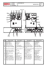
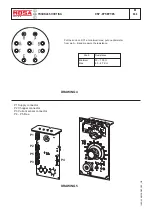
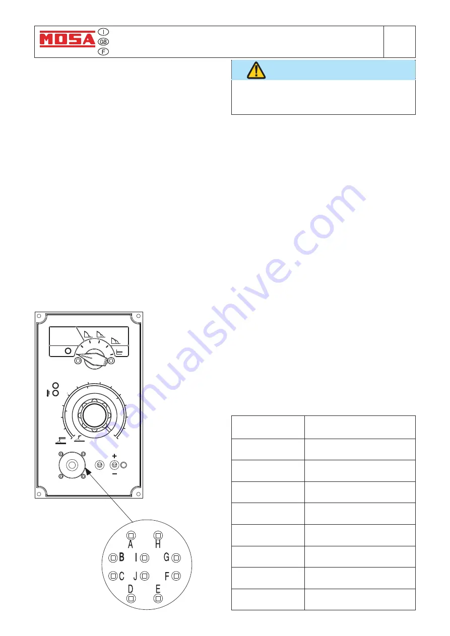
You can use the wire feeder only by respecting
the pin configuration as shown on the below
mentioned table.
WARNING
A (
electric ground
)
B
C (5 V d.c.)
D
E
F (5 V d.c.)
G
H (welding ground)
I (44 - 48V a.c.)
J (44 - 48V a.c.)
DESCRIPTION
To potentiometer RC1 "terminal
a"
To potentiometer RC1"central b"
To potentiometer RC1 "terminal
c"
short circuit with contact "C"
NAME OF
CONTACT
To switch "Polarity Inverter"
(Close for negative polarity)
Return from switch on CV welding
gun, 1-phase (44 - 48V a.c.)
Welding ground for d.c. voltmeter
on wire feeder
Voltage supply for wire feeder
CV
CC
STAND-BY
CONTACT
STARTING
REMOTE
CONTROL
70
20
25
40
100
WELDING DIGITAL CONTROL
130
160
190
220
250
280
310
340
370
400A
36V
16
10
30
ON
POLARITY
CURRENT CC
MAX
50%
INVERTER
RANGE
TIG
ARC FORCE
CELLULOSE 1
CELLULOSE 2
CC-STICK
CV-WIRE
11/10/04 M33_WDC_GB
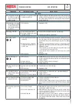
“WIRE FEEDER connected without remote
control connector”
Welding voltage is always present on welding
sockets and also VRD is active.
-Welding cable between the machine’s (9) welding
plug (+) and the wire feeder.
-Welding cable between the machine’s (10) welding
plug (-) and the piece to be welded.
The setting of the welding voltage is done by using
the knob on the front panel.
Summary of Contents for DSP 2x400 PS-PL
Page 38: ...DSP 2x400 PSX REV 0 11 05 M 53 Dimensioni Abmessungen Dimension 18 11 05 88412 I...
Page 42: ...DSP 2x400 PS PL REV 0 11 05 M 61 2 Stromlaufplan 28 11 05 78413 D...
Page 43: ...DSP 2x400 PS PL REV 1 02 11 M 61 3 Stromlaufplan 28 11 05 78413 D...
Page 44: ...DSP 2x400 PS PL REV 1 02 11 M 61 4 Stromlaufplan 28 11 05 78413 D...
Page 45: ...DSP 2x400 PS PL REV 1 02 11 M 61 5 Stromlaufplan 28 11 05 78413 D...
Page 46: ...DSP 2x400 PS PL REV 1 02 11 M 61 6 Stromlaufplan 28 11 05 78413 D...

