USE
WELDING DIGITAL CONTROL
M
33.
4
© MOSA
1.0-10/04
WIRE FEEDER CONNECTION
Model WF4
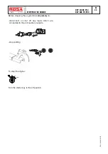
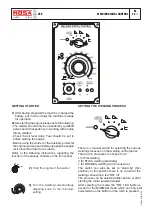
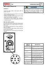
Connect the wire feeder to the welder with the
welder turned off:
- Welding cable between the machine’s (9) welding
plug (+) and the wire feeder.
- Welding cable between the machine’s (10) welding
plug (-) and the piece to be welded.
- Control/power cable between the machine’s
connector (X1) and the corresponding connector
on the wire feeder.
Start the machine welder
The “ON” LED will be off and will turn on only when
there is voltage at the welding plugs (and therefore
at the wire).
The voltage is only present when the welding torch
button is pressed.
The setting of the welding voltage is done using the
knob on the wire feeder.
The adjusting knob on the welder is automatically
inhibited.
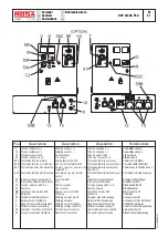
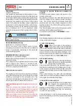
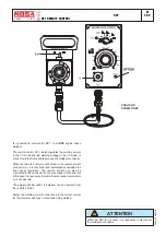
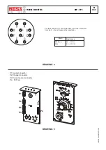
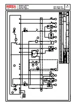
The connection of other brands of 42V AC wire
feeders to the front panel connection can be
done ONLY if wire feeder connector has the
same configuration as showed below.
WARNING
A (
electric ground
)
B
C (5 V d.c.)
D
E
F (5 V d.c.)
G
H (welding ground)
I (44 - 48V a.c.)
J (44 - 48V a.c.)
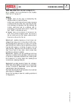
DESCRIPTION
To potentiometer RC1 "terminal
a"
To potentiometer RC1"central b"
To potentiometer RC1 "terminal
c"
short circuit with contact "C"
NAME OF
CONTACT
To switch "Polarity Inverter"
(Close for negative polarity)
Return from switch on CV welding
gun, 1-phase (44 - 48V a.c.)
Welding ground for d.c. voltmeter
on wire feeder
Voltage supply for wire feeder
11/10/04 M33_WDC_GB

