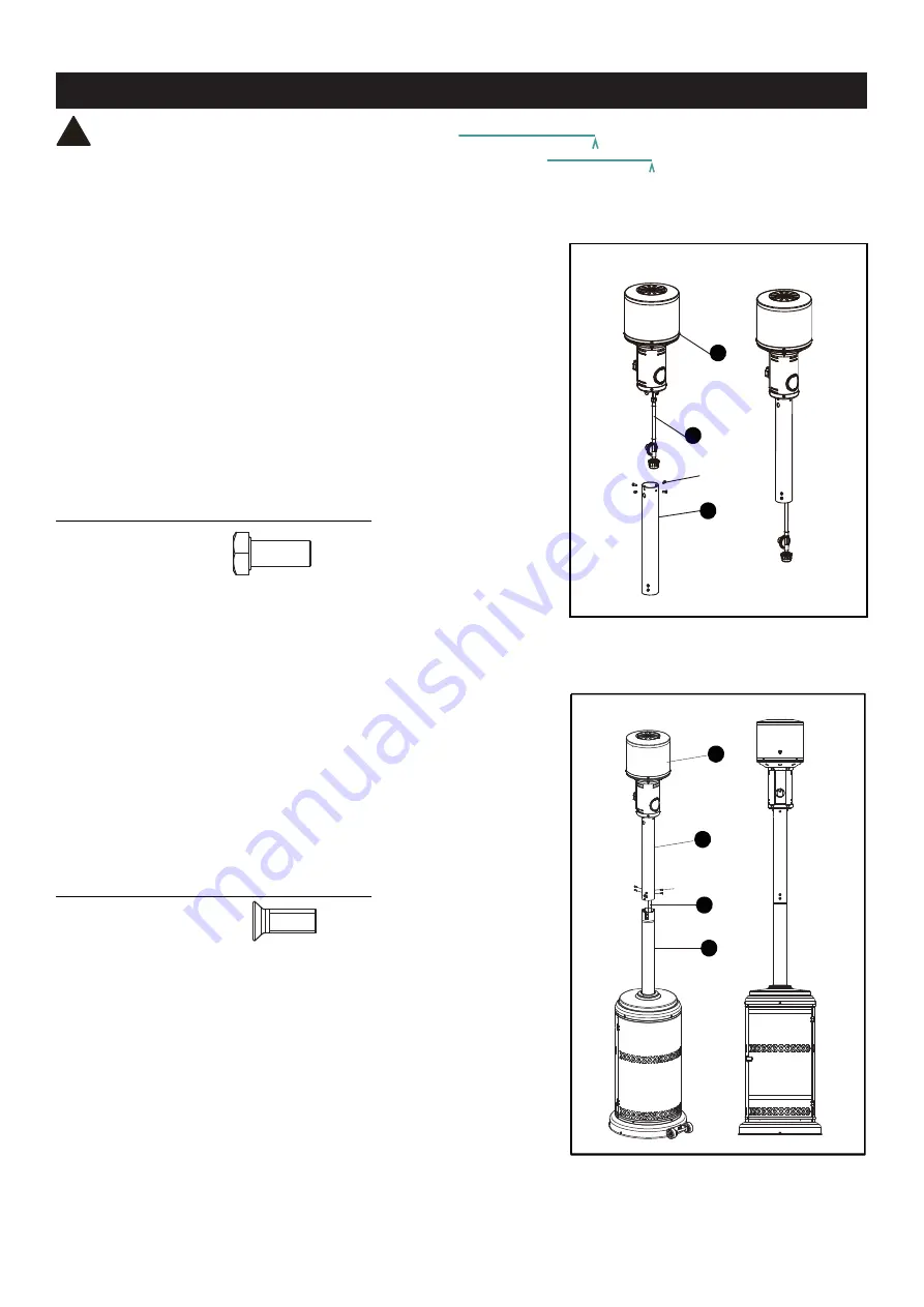
Place the upper pole (D) on the lower pole (E)
Insert gas hose and regulator (J) of the burner head (C)
into the lower pole (E).
tighten with (6) M5 x 12 flat bolts (EE).
Step 4
Step 3
Hardware Used
Hardware Used
DD
Step 4
Step 3
WARNING: THIS APPLIANCE REQUIRES INSTALLATION BY A COMPETENT PERSON.
PROPER ASSEMBLY IS THE RESPONSIBILITY OF THE INSTALLER.
ASSEMBLY INSTRUCTIONS
C
E
J
D
D
C
DD
EE
M6 x 14 Bolt
x 4
EE
M5 x 12 Flat Bolt
x 6
Insert gas hose and regulator (J) of the burner head (C)
into the upper pole (D), then tighten the burner head (C)
to the upper pole (D) with (4) M6 x 14 bolts (DD).
Note: Make sure the regulator goes through the pole.
J
Page 10 of 23
!


