Appendix F: Redundant Backup with TP64 and TPT-2 Transfer Panels
F-13
Moseley SL9003Q
602-12016-01 Revision J
healthy and router input 1 will be selected. If the main receiver fails, the line will go LOW,
and input 2 will be selected (the Standby receiver will then be active).
The Broadcast Tools switcher/router is configured internally with DIP switches to operate
from external control. The lid must be removed from the router to set the DIP Switch 5–6 to
the ON position for remote control.
The transfer control cable is available from Moseley for this configuration (203-12416-01).
However, a cable can be made from a shielded RJ-45 (Black Box P/N EVNSL60-0006). This
is a 6-foot cable that can be cut and the ends tinned to provide the RX XFER OUT signal
(RJ45 pin 6) for the indicated connection. Be sure to maintain the shield performance by
connecting to ground. The high RF levels in typical STL receiver environments can cause
problems.
F.5 Operation
F.5.1 Hot/Cold Standby Modes
Hot Standby (*preferred)
: Hot standby leaves both transmitters in the RADIATE ON
condition, and the TP128/TP64 controls the RF relay to select the active transmitter, thereby
decreasing switchover time. This is the preferred operating mode.
Cold Standby
: Cold standby can be used in situations where low power consumption is a
priority. In this mode, the TP128/TP64 will control the RADIATE function of each
transmitter, turning the RF output ON (in tandem with the RF relay) as required for
switching. This will increase switching time and a corresponding increase in data loss during
the switchover.
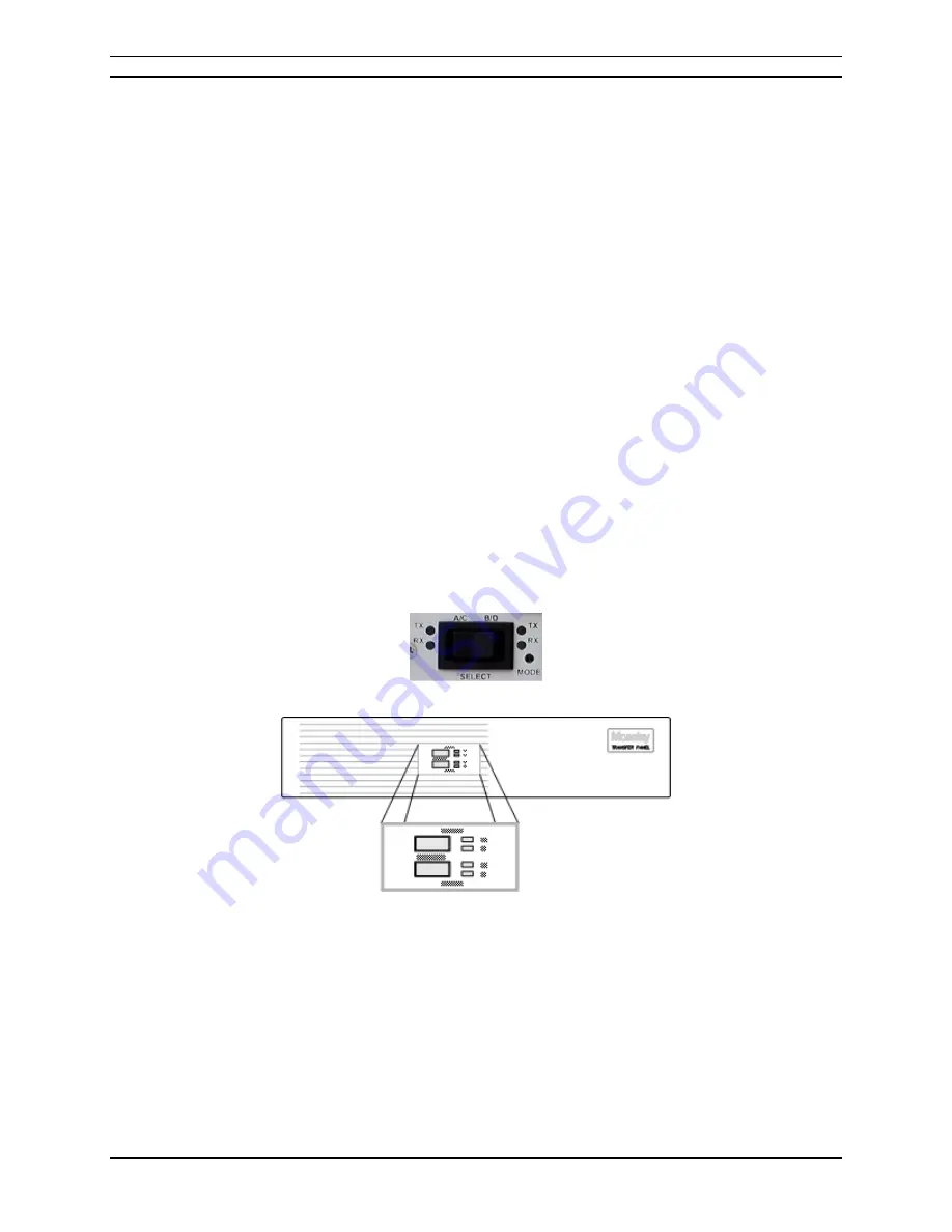
F.5.2 Panel Controls and Indicators
Figure F-9. TP128 Panel
Figure F-10. TP64 Front Panel
LED Indicators
Green: The indicated module is active and performing within its specified limits.
Yellow: The indicated module is in standby mode, ready and able for back-up transfer.
Red: There is a fault with the corresponding module. It is not ready for backup, and the
TP64 will not transfer to that module.
TRANSFER Switches
Summary of Contents for Starlink SL9003Q
Page 86: ...5 22 Section 5 Module Configuration Moseley SL9003Q 602 12016 01 Revision J ...
Page 90: ...6 4 Section 6 Customer Service Moseley SL9003Q 602 12016 01 Revision J ...
Page 110: ...A 10 Appendix A Path Evaluation Information Moseley SL9003Q 602 12016 01 Revision J ...
Page 118: ...D 2 Appendix D Microvolt dBm Watt Conversion 50 ohms Moseley SL9003Q 602 12016 01 Revision J ...


