7-2
Section 7: System Description
Moseley SL9003Q
602-12016-01 Revision J
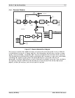
7-1 shows the operational block partitions that also represent the physical partitions within
the system.
All modules (excluding the Front Panel) are interconnected via the backplane which
traverses the entire width of the unit. The backplane contains the various communication
buses as well as the PA (Power Amplifier) control and redundant transfer circuitry. The
power supply levels and status are monitored on the backplane and the NMS/CPU card
processes the data.
The NMS/CPU card incorporates microprocessor and FPGA logic to configure and monitor the
overall operation of the system via front panel controls, LCD screen menus, status LED's
and the bar graph display. Module settings are loaded into the installed cards. Power-up
default settings are stored in non-volatile memory. LCD screen menu software is uploaded
into memory, providing field upgrade capability. A Windows-based PC interface is available
for connection at the rear panel DATA port.
7.2.1 Audio Encoder
COMPRESSED
LINEAR
FIFOs
COMPRESSED
LINEAR
FIFOs
24576
OSCs
33868.8
SPDIF
AES/EBU
R
L
AUDIO
MUX
TC
INPUT
Internal
TL
16
1024
1024 1536
32 384
XTAL
13107.2
PLL
DDS
DDS
X2
ENCODER
SOURCE
S81
CLOCK
MUX
16384
CLIP
GEN
CLIP LEDs
R6
R
L
I_M2
I_M5
I_M3
I_M4
M7,M8
M4,M5,M6
M1,M2,M3
1024 1536
ZEROES
R1,R2,M3
DATA
CLOCK
Analog Input Daughtercard
FRAME
SYNC
LINEAR
TL
TC = TRUNK COMPRESSED
= TRUNK LINEAR
R3
MUX
DECODE
ADDRESS
MUX ADDRESS
A2-A9
TRUNK
TRUNK
MUX
MUX
Front Panel
COMPRESSED
MODEM
LINEAR
MODEM
RS-232
TRANSLATOR
ASYNC TO
SYNC
CONVERTER
L & R
DIGITAL
AUDIO
AUX ASYNC
DATA
D1-D5,D7,R5
A/D
GENERATOR
SINE
R
L
D/
A
Front
Panel
Bargraph
R6
LEVEL
XLATORS
RATE
CONVERTER
SAMPLE
S52
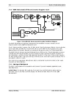
Figure 7-2. Audio Encoder Block Diagram
The Audio Encoder module directly receives and decodes the AES/EBU digital audio into a
digital stereo audio data stream. Optionally, the analog audio inputs can be used (located
on the Analog Input daughtercard), and these inputs are converted to 16/24 bit digital
stereo data. The SRC (sample rate converter) passes the digital audio data stream to a data
multiplexer while synchronizing/converting the incoming sample rate (30-50 kHz) to the
Summary of Contents for Starlink SL9003Q
Page 86: ...5 22 Section 5 Module Configuration Moseley SL9003Q 602 12016 01 Revision J ...
Page 90: ...6 4 Section 6 Customer Service Moseley SL9003Q 602 12016 01 Revision J ...
Page 110: ...A 10 Appendix A Path Evaluation Information Moseley SL9003Q 602 12016 01 Revision J ...
Page 118: ...D 2 Appendix D Microvolt dBm Watt Conversion 50 ohms Moseley SL9003Q 602 12016 01 Revision J ...


