Section 7: System Description
7-7
Moseley SL9003Q
602-12016-01 Revision J
7.3.1 Receiver Module
BPF
950 MHz
Diplexer
70 MHz
RF Input
944-952 MHz
RF AGC
IF Amp
IF Output
70 MHz
to QAM
Demod
Preamp
ALC
Loop Amp
ALC
Det
Atten
BPF
70 MHz
PLL
Loop
Filter
VCO
880 MHz PLL
Synth
Lock
Data
Clk
Enbl
Ref
ALC Control
12.8 MHz Ref Osc
uP
Synth Level
Synth Lock
NMS
Synth
Clk
Synth Data
Synth
Enbl
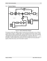
Figure 7-7. Receiver Module Block Diagram
The receiver handles the traditional down-conversion from the RF carrier to the 70 MHz IF.
Considerations are given to image rejection, intermodulation performance, dynamic range,
agility, and survivability. A separate AGC loop was assigned to the RF front end to prevent
intermodulation and saturation problems associated with reception of high level undesirable
interfering RF signals resulting from RF bandwidth that is much wider than the IF
bandwidth. The linear QAM scheme is fairly intolerant of amplifier overload. These problems
are typically related to difficult radio interference environments that include high power
pagers, cellular phone sites, and vehicle location systems.
Summary of Contents for Starlink SL9003Q
Page 86: ...5 22 Section 5 Module Configuration Moseley SL9003Q 602 12016 01 Revision J ...
Page 90: ...6 4 Section 6 Customer Service Moseley SL9003Q 602 12016 01 Revision J ...
Page 110: ...A 10 Appendix A Path Evaluation Information Moseley SL9003Q 602 12016 01 Revision J ...
Page 118: ...D 2 Appendix D Microvolt dBm Watt Conversion 50 ohms Moseley SL9003Q 602 12016 01 Revision J ...


