Section 5: Module Configuration
5-11
Moseley SL9003Q
602-12016-01 Revision J
XLR (male)
Ground
+
(HOT)
-
Figure 5-7. AES/EBU-XLR Decoder Connection
XLR (male)
Ground
+
(HOT)
-
Figure 5-8. SPDIF-XLR Decoder Connection
5.2.19 Analog Audio Gain and Input Impedance
Encoder (Analog In Card)
: Jumpers E2 and E5 set the left and right channel input
impedance. HI-Z is the default. You may set it to 600 ohm for external equipment
compatibility.
Jumpers E3 and E6 set the gain for the analog input stage. 0 dB is the default. You may set
the unit for up to 40 dB of additional gain if the external equipment has a low output level.
Decoder (Analog Out Card)
: Jumpers E3/E4 and E7/E8 set the left and right channel
output impedance. LO-Z is the default. You may set it to 600 ohm for external equipment
compatibility.
5.2.20 Data Channel Rate
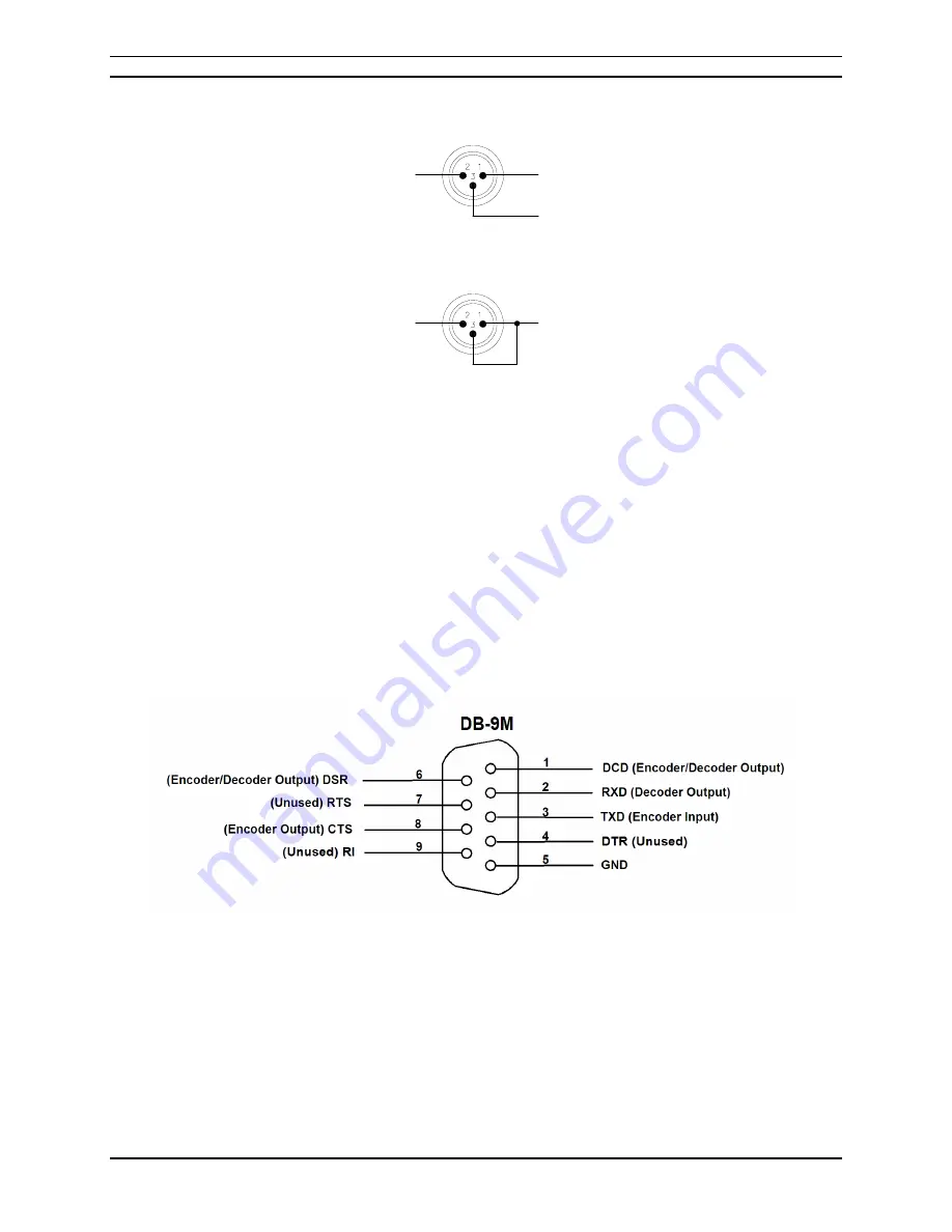
Switch S21 sets the data channel parameters for the card. Figure 5-9 defines the serial data
connection:
Figure 5-9. Data Channel Connector- DSUB (9-pin)
5.2.21 Board ID
Switch S22 sets the Board ID number and Base Address. DO NOT change these switches.
5.2.22 System Configuration
Switches S23, S31, and S52 set the board configuration for operation in the system. DO
NOT change these switches.
Summary of Contents for Starlink SL9003Q
Page 86: ...5 22 Section 5 Module Configuration Moseley SL9003Q 602 12016 01 Revision J ...
Page 90: ...6 4 Section 6 Customer Service Moseley SL9003Q 602 12016 01 Revision J ...
Page 110: ...A 10 Appendix A Path Evaluation Information Moseley SL9003Q 602 12016 01 Revision J ...
Page 118: ...D 2 Appendix D Microvolt dBm Watt Conversion 50 ohms Moseley SL9003Q 602 12016 01 Revision J ...


