Section 7: System Description
7-1
Moseley SL9003Q
602-12016-01 Revision J
7. System Description
7.1 Introduction
The SL9003Q consists of a transmitter (TX) and receiver (RX) pair of units that are matched
in frequency and modulation/demodulation characteristics. The following sections describe
the TX system, RX system, followed by sub-system components. Please reference the
accompanying block diagrams for reference and clarification.
This section follows the typical end-to-end progression of a radio system starting with the
TX baseband inputs, to the QAM modulator, followed by the up-conversion process and the
power amplifier. We then proceed to the RX preamplifier input, the down-conversion
process, followed by the QAM demodulator and baseband outputs.
7.2 Transmitter
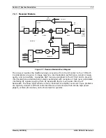
Figure 7-1. SL9003Q Transmitter System Block Diagram
The SL9003Q TX is a modular digital radio transmitter system that operates in multiple RF
bands (160-240, 330-512, 800-960, 1340-1520, and 1650-1700 MHz) and provides simplex
data transmission up to 2.048 Mbps increments in 8 kbps steps. The block diagram in Figure
Summary of Contents for Starlink SL9003Q
Page 86: ...5 22 Section 5 Module Configuration Moseley SL9003Q 602 12016 01 Revision J ...
Page 90: ...6 4 Section 6 Customer Service Moseley SL9003Q 602 12016 01 Revision J ...
Page 110: ...A 10 Appendix A Path Evaluation Information Moseley SL9003Q 602 12016 01 Revision J ...
Page 118: ...D 2 Appendix D Microvolt dBm Watt Conversion 50 ohms Moseley SL9003Q 602 12016 01 Revision J ...


