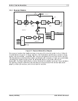
7-8
Section 7: System Description
Moseley SL9003Q
602-12016-01 Revision J
7.3.2 QAM Demodulator/IF Downconverter Daughter Card
IF Input
70 MHz
BPF
70 MHz
BPF
6.4 MHz
AGC Control
PLL
Loop
Filter
VCO
76.4 MHz PLL
Data
Clk
Enbl
Ref
IF Output
6.4 MHz
-10dBm
Synth Level
Synth
Lock
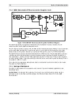
Figure 7-8. SL9003Q IF Downconverter Daughter Card Block Diagram
The QAM (Quadrature Amplitude Modulation) Demodulator module consists of an IF
Downconverter and a QAM Demodulator card.
The IF Downconverter receives the 70 MHz carrier from the Receiver Module via an external
semi-rigid cable and directly converts the carrier to 6.4 MHz by mixing with a low-noise
phase-locked LO. System selectivity is achieved through the use of a 70 MHz SAW filter.
The QAM Demod receives and demodulates the 6.4 MHz carrier. The demodulation process
includes the FEC implementation and de-interleaving that matches the QAM modulator in
the transmitter, and the critical “data assisted recovery” of the clock. This process requires
an ultra-stable master clock provided by an OCXO (oven controlled crystal oscillator) that is
accurate to within 0.1 ppm.
The output is an aggregate data stream that is distributed to either the MUX or the Audio
Decoder via the backplane.
7.3.3 Intelligent Multiplexer
The MUX is documented in a separate user manual. Typical broadcast applications are
described here:
6-Port Mux:
For discrete STL systems, the 6-port mux (with Ethernet option card) is
primarily used to interface and demultiplex the Ethernet data stream from the QAM
demodulator.
Summary of Contents for Starlink SL9003Q
Page 86: ...5 22 Section 5 Module Configuration Moseley SL9003Q 602 12016 01 Revision J ...
Page 90: ...6 4 Section 6 Customer Service Moseley SL9003Q 602 12016 01 Revision J ...
Page 110: ...A 10 Appendix A Path Evaluation Information Moseley SL9003Q 602 12016 01 Revision J ...
Page 118: ...D 2 Appendix D Microvolt dBm Watt Conversion 50 ohms Moseley SL9003Q 602 12016 01 Revision J ...


