Section 7: System Description
7-9
Moseley SL9003Q
602-12016-01 Revision J
7.3.4 Audio Decoder
FIFOs
13107.2
PLL
R
L
DECODER
SOURCE
Analog Out Daughtercard
FRAME
SYNC
LINEAR
M4
R1,R2
ZEROES
CLOCK
DEMUX
16384
16
M5,M6
1024
1024
1024-1536
32-384
TRUNK COMPRESSED
TRUNK LINEAR
MUX COMPRESSED
MUX LINEAR
R6
M4
TRUNK
LINEAR
M3
D1-D5
DATA
AUX ASYNC
24576
OSCs
33868.8
XTAL
LEVEL
XLATORS
FIFOs
A9-A2
MUX
ADDRESS
DECODE
ADDRESS
MUX
GENERATOR
SINE
M1,M2
CONVERTER
SAMPLE
RATE
S81
AES/EBU
SPDIF
L & R
DIGITAL
AUDIO
D/A
D/A
R
L
Analog Audio
LINEAR
MUX
COMPRESSED
MUX
COMPRESSED
TRUNK
LINEAR
MODEM
COMPRESSED
MODEM
ASYNC
CONVERTER
SYNC TO
TRANSLATOR
RS-232
Front
Panel
Bargraph
DDS
DDS
X2
I_R4
I_R1
I_R3
I_R2
M7,M8
ALL FREQUENCIES IN kHz
DATA
CLOCK
(MD1283)
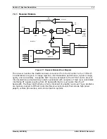
Figure 7-9. Audio Decoder Block Diagram
The Audio Decoder module accepts the data stream and the recovered clock from the
backplane (QAM Demod or the MUX). This data (compressed or linear) is fed to the FIFOs
(First In. First Out) buffers. The data is then passed through the FIFOs to an initial data
multiplexer. Sine wave and “zeros” test signal generators are available on the card (switch
selectable) for system testing.
Compressed
: The audio decoder add-on card decodes the compressed data per the
appropriate algorithm (ISO/MPEG). This decoded information is then passed on to the
Sample Rate Converter (SRC) via a second data multiplexer.
Linear
: Using embedded coding, the linear inputs received are analyzed and then
synchronized for transmission to the Sample Rate Converter via a second data multiplexer.
The second data multiplexer chip selects which of the three inputs (Compressed Audio
Decoder, Linear Frame Sync, or Internal Sine Generator) will be sent to the SRC. As an
option, zeros can also be sent through the multiplexer chip to test the noise floor.
The SRC receives the data stream via the second data multiplexer. This information is
compared to the clock rate determined at switches M7 and M8 for conversion to the final
output decoding segment.
Summary of Contents for Starlink SL9003Q
Page 86: ...5 22 Section 5 Module Configuration Moseley SL9003Q 602 12016 01 Revision J ...
Page 90: ...6 4 Section 6 Customer Service Moseley SL9003Q 602 12016 01 Revision J ...
Page 110: ...A 10 Appendix A Path Evaluation Information Moseley SL9003Q 602 12016 01 Revision J ...
Page 118: ...D 2 Appendix D Microvolt dBm Watt Conversion 50 ohms Moseley SL9003Q 602 12016 01 Revision J ...


