background image

Summary of Contents for TRC-15A

Page 1: ...INSTRUCTION MANUAL MODEL TRC 15A REMOTE CONTROL SYETEM KOSELEY ASSOCZATES INC Santa Barbara Research Park 111 Castilian Drive Goleta California 93017 Revised July 1975 805 968 9621 ...

Page 2: ... 23 B Control Demodulator 27 C Audible Metering Generator 29 D Subaudible Metering Generator 31 E Audible Metering Demodulator 33 F Subaudible Metering Demodulator 35 G Subcarrier Generator 37 H Subcarrier Demodulator 39 ADJUSTMENT 39 A Routine B Internal C Control Generator D Control Demodulator E Audible Metering Generator F Subaudible Metering Generator G Audible Metering Demodulator H Subaudib...

Page 3: ...system The standard TRC ISA uses a telephone line interconnection between the studio and transmitter sites This system is defined by referring s to it as the TRC 15AW When options are installed to enable sub carrier or other wireless techniques to be used it is referred to as the TRC 15AR II SPECIFICATIONS Number of metering channels Metering system input Calibration controls Calibration voltage s...

Page 4: ...ctor devices Operating temperature range Power requirements each end 19 inch vertical rack space Domestic shipping weight 600 a 0 dBm adjustable 300 Hz to 375 Hz 800 Hz to 1200 Hz 30 dB with 0 dBm send levels 2000 G nominal 1 5 volts peak to peak 26 kHz typical for monaural STL 110 kHz typical for composite stereo STL 20 Hz to 30 Hz Adjustable up to 6 volts peak to peak behind 600 2 67 kHz typical...

Page 5: ...mind that if the two units are interconnected with a telephone line the system is a TRC 15AJ or if wireless subcarrier inter connections are used the system is a TRC 15AR Connections which will be required at the studio unit are to the power source and either the telephone line for the TRC 15AW or the STL radio equipment for the TRC 15AR At the transmitter site these same connections will be requi...

Page 6: ... the TRC 15AR for wireless operation In a similar manner the metering signals may be returned from the transmitter to the studio by using a subcarrier As shown in Figure 3 the metering generator frequency modulates a subcarrier generator at the transmitter site This subcarrier generator is usually a part of the main FM transmitter As with the control signals the meter ing signal now rides piggybac...

Page 7: ...SITE TRANSMITTER SITE METERING DEMODULATOR I I I t i METERING METERING T GENERAToA SAMPLE INPUTS FiG I BASIC TRC ISA REMOTE CONTROL SYSTEM EQUIPMENT ILLUSTRATED COMPRISES THE STANDARD WIRELINE SYSTEM TRC 15AW ...

Page 8: ...ultiplex LControl Tone modulated by output from control tone STL receiver Metering Tone Metering Tone 20 80 Hz Fig 2 Basic Wireless FM version of the TRC 15A Equipment illustrated corn rises the standard wireless system TRC 15AR At A is an SCA P subcarrier generator usually a part of the FM transmitter At 8 is an FM SCA receiver external to the TRC 15AR ...

Page 9: ...ulated by metering tone L Subcarrier L Metering Tone modulated by metering tone Fig 3 Wireless FM version of the TRC 15AR Equipment shown is the same as in Fig 2 with added optional subcarrier equipment for metering return A subcarrier generator been added for telemetry only service at and an internal subcarrier has been added for demodulation of this subcarrier at 5 ...

Page 10: ...modulate it to recover the metering signal This signal is a replica of the original metering signal generated at the transmitter site It is internally routed to the metering demodulator in the TRC 15A R studio unit This added sub carrier demodulator at the studio site is an available option which may be added to the standard wireless TRC 15AR C Wireless AM Figure 4 illustrates a modification of th...

Page 11: ...TROL from STL receiver TONE AM broadcast METERING signal returning to studio 1 GENERATOR METERING TONE Fig 4 Wireless AM version of the TRC 5AR Note the similarity to the Fig 32 At A is a standard broadcast AM transmitter and at B is an AM receiver tuned to that frequency TRC 15AR equipment involved is the standard wireless system TRC 15AR ...

Page 12: ...TL transmitter multiplex or subcarrier input If the TRC 15AR internal subcarrier generator is not used it is replaced by a jumper terminating board and the control output connector will deliver the control tone itself This tone may be routed either to an external subcarrier generator at the studio or it may be applied directly to the modulator of some other system whose output is ultimately at the...

Page 13: ...REAR OF STUDIO UNIT 300 0 120 OR 240 VAC INE 1 TELEPHONE LINE POWER INPUT 120 OR 240 VAC REAR OF TRANSMITTER UNIT I I TELEPHONE LINE FIG 5 TELEPHONE LINE INTERCONNECTIONS ...

Page 14: ...IN J I CONT OUT n I0000000 L RECEIVER METERING INPUT FROM TELEMETRY OR MONITOR REAR OF TRANSMITTER UNIT __ METERING OUTPUT TO TRANSMITTER OR SCA GEN POWER INPUT 0 0 0 0 0 0 0 120 OR 240 AC 43 CONTROL INPUT FROM STL RECEIVER FIG 6 WIRELESS INTERCONNECTIONS ...

Page 15: ...nsmitter units have been mounted in their respective racks or cabinets and the electrical interconnections have been made the next step is to check that control signals originating at the studio are received correctly at the transmitter Likewise the metering signals must be satisfactorily returned from the transmitter to the studio site It is advisable at this point to have made no con nections to...

Page 16: ...transmitter Subcarrier demodulator input at studio site used for metering driven by FM receiver Adjustable up to 6 volts peak to peak 1 5 volts peak to peak of subcarrier Control signal direct output at studio 1 5 volts peak to peak connects to external subcarrier generator Control signal direct input at trans mitter site driven from STL via external subcarrier demodulator 1 5 volts peak to peak M...

Page 17: ...control metering input be removed The target output voltage is 2 volts DC with a 1 volt mini mum and a 10 volt maximum Less than 1 volt may not allow full scale deflection of the studio meter and more than 4 volts may result in difficult setting of the calibration controls This assembly is avail able from Moseley Associates as Type PVK 1 or PVK 2 In Figure 7 B a shunt resistor in the vicinity of 1...

Page 18: ... RFC mn RI RZ i 83 DERIVING PLATE VOLTAGE SAMPLE II I I 0 LATE I URRENT SAMPLE UTPUT I FIG 7 DERIVING P LATE CURRENT SAMPLE ...

Page 19: ... I I u 0 TRANSMISSION SCREW FIG 8 ...

Page 20: ...ency monitors are generally low of the order of 25 microamperes at low voltage in the case of a typical reflectometer and in the case of frequency monitors an offset adjustment may be required no input results in half scale deflection Both of these complications are solved by using a DC amplifier such as the Moseley Associates Type DCA 1 The DC amplifier is connected between the reflectometer or m...

Page 21: ...g the LOWER button will energize the 12 VAC relay coil Proceeding to Channel 4 and pressing the LOWER button will cause the same effect as pressing the push button shown on the drawing There are no connections inside the TRC 15 which would connect any of these channels to one another This gives great flexibility in the control system since various voltages AC and DC etc may be mixed Nevertheless i...

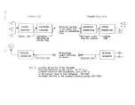
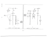
Page 22: ...r 311 RAISE FIG S SIMPLIFIED cor4TRo CONNECTIONS IN THE TRC 15 ...

Page 23: ...REAR OF TRANSMITTER UNIT 24 DC RELAY COIL 24VDC 1 3 PUSHBUTTON 711 t 12VAC II 12 AC RELAY COIL FIG IO SIMPLE EXAMPLES OF CONTROL CIRCUITRY EXTERNAL TO THE TRC 15 21 ...

Page 24: ...e throw relay contact When the con trol system is operational the fail safe relay internal to the TRC 15A transmitter unit is energized and a pair of terminals on the rear of the transmitter unit is closed When a failure in the control system occurs the normally closed fail safe terminals are opened These terminals should be connected in the transmitter control system in a manner that will take th...

Page 25: ... This disconnects the studio from the system To go to a new channel press the ADVANCE button RAISE and LOWER buttons Fontrol their respective relays just as if they were being controlled from the studio The selected channel can be deter mined by observing the front panel readout lamps After finishing calibration or other checks at the transmitter site be sure to press the REMOTE button to allow st...

Page 26: ...OR COUNTER COUNT e RAISE ENABLE PULSE S RECOUNT START I SINGLE PULSE LOWER ENABLE I OUTPUT PULSES AMP LOWER CLOCK GEN FREOUENCY CLOCK 60 Hz 60HZ PULSES PULSE GEN SINE OUTPUTS TO TEL LINE TO SUBCARRIER OPTION FIG 11 BLOCK DlAGRAM CONTROL GENERATOR ...

Page 27: ...esets the channel counter at the studio a nd is also sent to the transmitter site At both locations the channel selecting elec tronics returns to the start or calibrate position Immediately after this occurs the advance generator generates a series of pulses which drive the advance counter This continues until the advance counter develops a binary number which agrees with the number selected by th...

Page 28: ... PULSE TONE OR FM SANDPASS L M TER WIDTH SUBCARRIER DEMODULATOR DETECTORS DEMODULATOR FILTER DEMOD RAMI TUNING ADJ RAISE RAISE LOWER LOWER RESET a ADVANCE CHANNEL RELAY DRIVERS AND RELAYS FIG 12 BLOCK DIAGRAM CONTROL DEMODULATOR ...

Page 29: ...t a frequency of approximately 500 Hz The various commands are sent as pulses of modulation using different pulse widths or durations They are separated by using pulse width detectors A series of four such separators determines whether the pulses are for resetting for advancing to a new channel or for operating the Raise or Lower relays An input control tone level sensor is used to operate the fai...

Page 30: ...TERING VOLTAGE TO TEL LINE DC 0 LOW PASS b OUTPUT SAMPLE w CONTROLLED ISOLATOR AMPLIFIER FILTER AMPLIFIER TO SUBCARRIER INPUT OSCILLATOR GENERATOR 0 I VDC f I _ PINION FREQUENCY LEVEL ADJ FIG 13 AUDIBLE METERING GENERATOR ...

Page 31: ...1200 Hz representing full scale deflection of the studio meter upon application of a 1 volt DC sample This entire portion of the module including its power supply and regulators is floating with no connection to ground To translate the output of the voltage controlled oscillator down to ground an optical isolator is used The output of this device is a square wave which is applied to a low pass fil...

Page 32: ...Hz _I METERING DC VOLTAGE FREQUENCY OUTPUT TO SAMPLE 4 CONTROLLED AMPLIFIER ISOLATOR LOW PASS OUTPUT INPUT DIVIDER OSCILLATOR 240 FILTER AMPLIFIER SUBCARRIER GENERATOR 0 I VDC LEVEL ADJ FIG 14 SUBAUDIBLE METERING GENERATOR ...

Page 33: ...presenting full scale deflec tion of the studio meter upon application of a 1 volt DC sample This entire portion of the module including the power supply and regulators is floating with no connection to ground To translate the output of the voltage controlled oscillator down to ground an optical isolator is used The output of this device is applied to an integrated circuit divider chain for freque...

Page 34: ...ND PASS BAND PASS FILTER FILTER AMPLIFIER I LIMITER PULSE COUNTING DC LINE OR LINE OR FM DEMODULATOR AMPLIFIER SUBCARRIER DEMODULATOR I 9 I LIMITER PULSE COUNTING DC FM DEMODULATOR AMPLIFIER b FULL SCILE MUTE METERING TONE SENSOR FIG I5 AUDIBLE METERING DEMODULATOR _ I I ...

Page 35: ...ter and a level sensing circuit This latter circuit allows the front panel metering read lamp to be energized The limiter drives a pulse counting demodulator employing a Schmitt trigger and monostable multivibrator The output of this demodulator is applied to a DC amplifier which is arranged so as to provide considerable control over the meter ballistics In addition the input level sensor is conne...

Page 36: ...I 1 I TONE FROM ACTIVE INTERNAL 4 LOW PASS w OR EXTERNAL I 1 SUBCARRIER DEMODULATOR if L OR AM RECEIVER OAIN CONTROL AMPLIFIER _ I FM DEMODULATOR AMPLIFIER A FULL SCALE ZERO I DJ I LAMP FIG 16 SUBAUDl6LE METERING DEMODULATOR ...

Page 37: ...o the following stages This stage is a Schmitt trigger circuit which shapes the sinusoidal tone to a square wave required to trigger the following monostable multivibrator The monostable and associated circuitry form the last stage of a pulse counting demodulator The output of this demodulator is applied to a DC amplifier which has a cutoff frequency of about 5 Hz In this way the 20 Hz to 30 Hz me...

Page 38: ...METERING OR FREOUENCY SUECARRIER CONTROL 4 MODULATED b KEYED LOW PASS 4 OUTPUT OUTPUT TONE OSCILLATOR SUFFER FILTER AMPLIFIER TO STL OR EXCITOR I I 4 OUTPUT LEVEL AN FIG 17 SUBCARRIER GENERATOR ...

Page 39: ...r is applied to a buffer amplifier Th s buffer can be keyed on or off by means of a 5 volt signal applied to a muting input terminal This signal if used is normally supplied by the control demodulator module By removing the keyer transistor the subcarrier will always remain on The output of the buffer is applied to a low pass filter for removal of unwanted harmonics of the subcarrier The filter ou...

Page 40: ...INPUT FROM SUBCARRIER 4 KHZ PULSE LOW PASS LINEAR STL OR FM EXTRACTION b LIMITER OUTPUT COUNTER AMPLIFIER RECEIVER BANDPASS FILTER FIG I8 SUBCARRIER DEMODULATOR ...

Page 41: ...tering signals in the 20 Hz to 30 Hz range and control signals in the 300 Hz to 400 Hz range are passed by this filter The output of the filter is built up in amplitude by the output amplifier The adjustments on this module are for demodulator tuning and output level adjustment The subcarrier bandpass filter is also tuneable VII ADJUSTMENT A Routine The only controls on the TRC 15A which are inten...

Page 42: ...armonic of the power line 2 Control tone amplitude The amplitude of the control tone may be adjus ted normally to a level of 0 dBm into the telephone line Use a VTVM calibrated directly in dBm for this adjustment or an AC VOM as an alternate Should excessive RF or noise appear on the line use the grey test point on the control generator board If this is done set for an indication of t6 dBm The dro...

Page 43: ...gestions listed under Control Generator to the grey test point on the audible metering generator board Set the 860 Hz adjustment for an indication of 800 Hz The acceptable limits are 780 Hz to 830 Hz 2 1000 Hz adjust This control sets the sensitivity of the voltage controlled metering oscillator When the calibration voltage is applied to the unit this control is adjusted for a metering oscillator ...

Page 44: ...ied to the meter movement After the overshoot adjust ment is made the acceleration is adjusted As it is advanced from the starting counterclockwise extreme it will be noticed that the meter movement is more and more responsive Finally the meter overshoots and the control may be backed off somewhat The meter movement rise time is quickened if a small overshoot is allowable H Subaudible Metering Dem...

Page 45: ...lied to the subcarrier demodulator adjust the four inductors for maximum subcarrier ampli tude coincident with minimum ripple or modulation as observed with an oscilloscope connected to the yellow test point This filter realignment should not be necessary unless a component has been replaced 1 Demodulator tuning This control is used to set the operating point of the pulse counting discriminator Co...

Page 46: ...rms are shown on the schematics at key points By comparing the suspect unit with the measurements given on the schema tics the problem can usually be localized quickly 3 If an integrated circuit is suspect carefully remove the original and plug in the new one in the same direction These devices are installed one way only and plugging in the new one backwards may damage it The key on these IC s is ...

Page 47: ...a module level Then a replacement module is mailed out The second route is a return of the complete both units system to the factory Obvi ously this method is more time consuming 8 Do not return equipment without having first contacted the factory Should communications be necessary regarding the TRC 15A address your correspondence to Customer Service Department MOSELEY ASSOCIATES INC 111 Castilian...

Page 48: ...I If I I I T I d P _I r i ...

Page 49: ...OARD 51 A 5424 e 5CHEMATIC 91 L 6560 STUDIO UNIT CONTROL TERM I COMPONENT LAYOlJT CJ 0 WER SUPPLY g TRC lb TDL PRACT t l 32 xX f 030 xxx I OlO L e l 2 DWN c lt 8 4 72 SCALE FULL iit ii CHK ENB Tpy I 2 0 A 2 3 3 5 1 ...

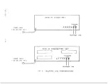
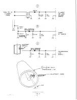
Page 50: ... _ i _ I 1 REMOTE TERMlNALt ...

Page 51: ...I UNLESS OTHERWISE SPECIFIED CAPACITOR VALUES ARE IN YIC 2 PC 80ARO 5185716 3 SCHEMATIC 9lC6561 q FLEX CIRCUIT NO 5185721 ENGAGED OVER PINS PUSH CIRCUIT OOWN TO REST ON THE PLASTIC PIN STRIPS SOLbER SECURELY IN PLACE 6ER6 65560 431 STRIP 3 PLC LONG PINS INSERTED IN BOARD CUT OFF PINS BELOW BOAR0 J AFTER SOLDERING IN PLACE I ...

Page 52: ...HEMATIC 31 C 6561 Ah AA 1 I I I I ELEVATP RZ R z 9 lL Ll ANO CRIZ CR16 TRC 15 REMOTE XMTR wom L m COMPONENT LAYOUT PWR SUPPLY 600 TOL rRACT l a xX f a xXx r ow if 1 OWN jL 1 a 2 72 SCALE Fu LL CHK F x Y 19 9 7 EN0 47 ew 2OA 2336 IAl ...

Page 53: ...OTES I P C BOARD SIA5716 2 SCHEMATIC 9lC656 I CUT PINS COMP SIDE TYP 32 PLC L a COMPONENT LAYOUT METERING INPUT BRD TRC I5 R T TOL FRACT f l 32 xX JY xxx c ow L Ztll r DWH 6M j 2G 76 SCALE CHK FXY 3lMAR7 ...

Page 54: ...LEX 22 03 2201 WAFER 8 REO E l 76 DIETERICH POST 21118 002 FILM Ill1 g A II II g NOTES I SCHEMATIC 91 C 6561 2 P C BOARD 51 A5719 COMPONENT LAYOUT TRC I5 TRANS CALIBRATIONBO TOL FRACT f l 32 xx oJo xxx c OlO L l P WN L I 25MAR77 SCALE FU LL ...

Page 55: ...REAR VIEW NOTES I UNLESS SPECIFIED WIRE IS Y26 DIETERICtt QST CLEARPRI 0 UC9 Na 0 0 2 aa Om In WIRE lDE TIFICATION TRC IS XMiR UNIT PARTITION ...

Page 56: ...TRANSMITTER UNIT CONTROL DEMODULATOR 51 c 5419 I I I I CONTROL GANOPASS 51A5423 FRONl STUDIO UNIT CONTROL GENERATOR SUBAUDIBLE P C BOARD LOCATIONS ...

Page 57: ...f h I ...

Page 58: ...5 PIN I3 RESET OR DELAY I C5 PIN 4 COUNTING COUNTiN 1 IC9 PIN8 COUNT im I CONTROL IC4 PIN 6 POST COUNT DELAY DELAY IC6 PIN4 CONTROL ENABLE I CONTROL ENABLED AT THIS TIME TRC I5A CONTROL GENERATION Tl MING DIAGRAM TOL FRACT f l 31 xx f uo xxx 2 OlO L f l Z OWN 1 L 1 lISJULY7d SCALE N 0 NE 1 76 DIET f ICti POST CL EARPRINT 1020 8 ...

Page 59: ... 4154 2 I 5 LISTED AS 741 ARE 5N72741 P 3 u DENDTE 5 SELECTED VALUES 4 P C BOARD 51 A BeZI 5 SCHEMATlC 91 C 6562 STUDIO CONTROL TERM COMPONENT LAYOUT CONTROL GENERATOR TRC I5 T0l 1 FRACT f l 32 xx f mo xXx e PlO L et 1p OWN 18 3 72 SCALE FULL CHK I XY 92 z ENQ i d iT 20A2337 IBl c P s 71 DIETERICH POST CLEARPRINT 1020 S ...

Page 60: ...47 t 44 t 43 I I I I 247 t 44 I 247 t 42 DEMODULATOR R CR I n 2 15V IW Lc2 J c4 J C8 J C8 I I IN4744 T 2S8 T 30 T 35 I IK I CR2 I I NOTES I UNLESS OTHERWISE SPECIFIED RESISTOR VALUES ARE IN OHMS I t W 10 CAPACITOR VALUES ARC IN MICROFARADS 2 t DENOTLS DWQ tc 1400 3 P C BOAR0 II A 5423 4 COMPONENT LAYOUT 20A 2338 REMOTE TERM XMTR SCHEMATIC TRC I5 CONTROL BANDPASS FILTER ...

Page 61: ... 10 CAPALITO dALUE5 AME IN MILROFAR DS 2 P L BOAR0 41 A 94 23 3 5LH EMATIC 91 A 6563 4 t OENI TE D o 2C 1403 REMOTE TERM XMTR COMPONENT LAYOUT CONTROL BANDPASS FILTER TRC I5 TOL FRACT 1 l l xx f OY xXx I MB Lctlp OWN _ 9119 72 SCALE FULL CHK F X Y X X EN JO 2 5 72 2OA2338 ...

Page 62: ...I I I I ...

Page 63: ... 45v I ...

Page 64: ... _ I ...

Page 65: ... L I I TYPICAL COMPARATOR OUTPUT DUMP 091 3 I I I R E A D MONOSTABLE IC9 I DUMP DELAY 06 I h fc DUMP TRC 15 CONTROL DEMODULATION TIMING DIAGRAM TOL fRACT 1 22 xx 020 xxx 2 OlO L c 1 WN FX Y I3 JUL76 SCALE WK INQ 7 Js JLL 16 92A 1189 I 1 76 DIETERICH POST CLEARPRINT 1020 9 ...

Page 66: ... __ 1 J ...

Page 67: ...R VALUES ARE IN OHMS I 2 w IO A CAPAC I TOR VA LIJES ARE IN MICROTARAD5 D tODES ARE IN 4154 2 I c 5 LISTED AS 741 ARE 5N72f4I P 3 P c 6OARD 51 A 5416 4 S CHEMATIL 9lC 656s TRC 15 REMOTE XMTR COMPONENT LA AUD MTRG GEN TOL IRACT i l J xx f 010 xxx OlO 4 t l 1 1 DWN 1 ix 1s 2 721 SCALE FULL ...

Page 68: ... 1 ...

Page 69: ...EW IOX CAPACITOR VALUES ARE IN MICROfARADS DIODES ARE IN 4154 2 I C S LJSTLD AS 741 AKE 5N 72741 P 3 f DENOTES DRG i C 1400 045 4 P C BOARD BIA 5420 5 LCHEMATI C 91 L 6566 TRC I5 CONTROL STUDIf COMPONENT LAYOUT SCU AUD MTRG DEMOD TOL FRACT 3 l 32 xx oa xXx 2 JlO L rt ...

Page 70: ...I I C l l I ...

Page 71: ...APACITOR VALVES ARE IN MICROFARAD5 DIODES ARE IN 4151c 2 I C S LfSTED AS 741 ARE 5N7Z74t P 3 P C BOARD 61A 5417 4 SCHEMATIC YIC 6567 TRC I5 REMOTE XMTk COMPONENT LAYOUT SUBAUD MTRG GEN TOL FRACT k l 12 xx oJo xxx OlO 6 l 2 OWN hf 7 31 72 SCALE FULL CHN ENC j f 2 0 A 2 3 4 2 I0 ...

Page 72: ...l c I I ...

Page 73: ...5 ARE IN MICROFARADS DIODE5 ARE IN 4154 2 l C S LISTED A5 741 ARE SN 72741 P 3 P C BOARD 5lA 5622 4 5 CHEMATI C 9lC 6568 TRC I5 CONTROL TERM COMPONENT LAYOUT SUBAUDIBLE METERING DEMOD TOL FRACT 2 l 32 xx zlz 030 xxx t 110 L r l Z OWN _ h 4 z 72 SCALE FULL CHK 6 XY 9126172 s Q JCi Z7Jer72 20A 2343 ...

Page 74: ... 1 r I I t 3309 I ...

Page 75: ...19 0 0f 1 75cf PF 1 YIOPF 1 37 mh 1 4 7mh 2 1 3qnHz 560pf I4TOOPF 1 560PF I 33mh I 3 4 IMHZ560pf 8 4 6TWHr 33opf 27OOPF ___ r 95KHr 24DRf 22OOPF 0 6 IIOUHZ 200 f 15OOPF 390PF 4 Tmh 11 7 135KHr i f I3OOPF3OOPF I Omh 9 IBSKHr 20pf ZOOPF ICOPF 6BOuh 9 152KHz 2Wpf BZOPF 51 PF 22mh I 5 mh COMPONENT LAYOUT SUBCARR GEN TOI FAACT z l 12 xx 2 olo xxx 010 1 IT 1 z OWN 7 31 72 SCALE F ULL CHK F i 9 Z6 17 ENG...

Page 76: ... 1 ...

Page 77: ... w 10 c P cIToa VALUES ARC 111 YICIOCARADS YRANSISTOAS ARE 2k bOS DlODtSA11S IMIIS4 a l C OAriD 8lASOOl s ICHEYATIC 91 C SST0 4 f REOUCNCY DLTLllYlMCO COYPONEWT SEE S4A4010 f TRC ISAR t COMPONENT LAYOUT SU6CARRIER DEMODULATOR TO1 fRAC1 t l as xR t r m 2 Air 4c 1m OWN 1 u IT 11 73 8cMRa DULL ...

Reviews: