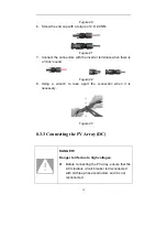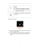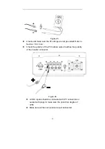
19
Figure 7
7 Installation
7.1 Safety Instructions
DANGER!
Improper installation may cause fire or explosion.
•
Do not install the inverter on flammable and explosive
construction materials.
•
Make sure there is no electrical connection before installation.
CAUTION!
Improper carry may cause injury.
•
Avoid getting injury by improper carry.
•
Select a firm mounting surface.
•
Use proper tools for installation.
•
At least two people are suggested to coordinate for the
installation.
CAUTION!
HOT!
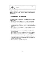
NOTICE!
The inverter output power decrease is usual in the
condition of thermal protection, but if it occurs
frequently, you need to check the heat sink or consider
putting the inverter in the place where have better air
flow, and if output power decreases caused by electrical
problem, please ask for professional supports.
Summary of Contents for ST5KTL
Page 1: ...ST5KTL ST6KTL ST7KTL ST8KTL V2 0...
Page 2: ......
Page 5: ...1 1 1 1 2 1 3 1 3 A 1 2 3 1 ST5 8KTL L B ST5 8 1 ST5KTL KTL C 1 L ST6KTL ST7KTL D ST8KTL...
Page 6: ...1 3 2 2 IEC 617 730...
Page 7: ...1 3 3 D DC D 3 DC DC 5...
Page 8: ...4...
Page 9: ...C TU CQ E UV QC 5 CE TUV CQC...
Page 10: ...2 2 2 2 1 2 6 2 3...
Page 12: ...S 5 ST5K ST5KTL 24kg 8 KTL ST6KT ST6KTL 24kg TL ST7KTL 1 L ST7 24 ST8KTL 7KTL 4kg ST8KTL 24kg...
Page 13: ...3 A B C D E F G RS 9 2 S485 1 1 4 8 4 2 1...
Page 14: ...A D G 10 6 B E 6 C F...
Page 18: ...5 WiFi RS 14 S456 GPRS...
Page 19: ...6 15 7 7...
Page 20: ...7 7 1 16...
Page 21: ...7 2 45 C 2 C 60 C 17 2000 8 15 25 C 11 60 C...
Page 22: ...7 3 7 4 3 4 4 18 9 10 8mm m...
Page 23: ...40 8 10mm 45mm m 19 11 12...
Page 24: ...7 5 5 14 20 13 4...
Page 25: ...7 6 6 LCD D 21...
Page 26: ...8 8 8 2 A B C D E F 1 2 RS W S485 WIFI 22 15 7...
Page 27: ...8 3 8 3 3 P 1 MPPT PV T 23 MPPT PV 16 V1 PV2 MPP PT...
Page 28: ...MPP 8 3 1 100 V PT 2 17 M DC 23 MC4 MC4 24 PV MPP IP68 4 MPP 22 A V1 PT A DC PV2 MC4...
Page 29: ...1 2 3 4 5 7 25 17 18 19 7 8 9...
Page 30: ...6 7 8 2 6 2 9 9NM 26 20 2 0 1 22 23...
Page 31: ...8 3 3 P PV PV 27 V 110 27 00Vdc O OFF...
Page 32: ...PV PV PV 24 25 26 IP65 V 28 5 PV 6 PV IP68 OF FF 1 3 2...
Page 34: ...8 4 2 30 1 5 4 2 5...
Page 35: ...4 2 2 28 29 31 27 30 30 31 2 29...
Page 36: ...32 30...
Page 37: ...9 9 9 1 1 LED 1 1 LED1 Off On 33 LED 31 9 9 M MPPT...
Page 38: ...9 1 9 1 9 2 1 2 LED2 1 3 LED3 2 LCD Off On Off On LCD 34 10 1 32 0 1 L 30 LCD LCD LCD...
Page 41: ...F17 F18 F20 F25 F27 F28 F29 F30 F33 F36 F49 F51 F52 F62 F63 F65 F66 37 PV1 PV2 Boost AD ARM...
Page 44: ...10 2 2 WiF WiFi WiFi 38 RS48 i W 40 Web 5 USB 39 RS485 WiFi W bbox P PC WiFi PC...
Page 45: ...Wi Wifi ifi 41 40 W 41 Wifi Wifi Wifi...
Page 46: ...11 LED3 42 14 LCD...
Page 47: ...DC 14 C 43...
Page 48: ...12 12 12 12 13 12 1 2 3 F to 158 4 24 F 44 25 5 70...
Page 49: ...13 S 400 ST5KTL ST 756 5188 a b c d e T6KTL ST7 45 7KTL ST8K 5 KTL...
Page 51: ...Solar On Grid Inverter ST5KTL ST6KTL ST7KTL ST8KTL User Manual Version 2 0 EN...
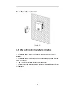
Page 76: ...24 Figure 12 7 5 Fixed the Inverter on the Wall Mount the inverter to the bracket Figure 13...


