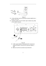
•
F
term
PV2
•
O
and
time
•
O
EMC
dev
8.3
Foll
con
Not
·
T
pro
tech
•
A
prov
•
B
PV
Th
the
Maximum
voltag
1,100 V (
No
or instance
minal and th
2 terminal, i
One string c
d can’t be co
e.
Otherwise, th
C directive
vices), and w
3.2 Assem
ow the step
nector.
ices:
The assem
fessional t
hnician.
All PV string
vided by the
Before conn
array match
he open circ
e maximum
input
ge
(DC)
o mixed PV
e, if the posi
he negative
it is called a
an be only
onnected w
he inverter
(directive o
will forfeit its
mbling t
ps showed
mble of DC
technician
s should be
e manufact
ection, mak
hes the “DC
28
cuit voltage
m input volta
Maxim
V connectio
itive pole of
pole of the
a mixed con
connected
with two pair
will not com
on the electr
s operating
he DC C
on Figure 2
connector
or under t
e connected
urer.
ke sure the
C+” and “DC
of the PV s
age of the in
mum input
trac
22 A
ons
f a string is
e same strin
nnection.
with one pa
r of PV term
mply with the
romagnetic
license.
Connecto
20-22 to ass
r should be
the guide o
d to the DC
polarity of t
C-“symbols
strings cann
nverter.
current pe
cker
(DC)
connected
ng is connec
air of PV ter
minals at the
e requireme
c compatibil
ors
semble the
e operated
of professio
connector
the output v
.
not exceed
er MPP
with PV1
cted at
rminals
e same
ents of the
ity of
DC
by
onal
which is
voltage of
Summary of Contents for ST5KTL
Page 1: ...ST5KTL ST6KTL ST7KTL ST8KTL V2 0...
Page 2: ......
Page 5: ...1 1 1 1 2 1 3 1 3 A 1 2 3 1 ST5 8KTL L B ST5 8 1 ST5KTL KTL C 1 L ST6KTL ST7KTL D ST8KTL...
Page 6: ...1 3 2 2 IEC 617 730...
Page 7: ...1 3 3 D DC D 3 DC DC 5...
Page 8: ...4...
Page 9: ...C TU CQ E UV QC 5 CE TUV CQC...
Page 10: ...2 2 2 2 1 2 6 2 3...
Page 12: ...S 5 ST5K ST5KTL 24kg 8 KTL ST6KT ST6KTL 24kg TL ST7KTL 1 L ST7 24 ST8KTL 7KTL 4kg ST8KTL 24kg...
Page 13: ...3 A B C D E F G RS 9 2 S485 1 1 4 8 4 2 1...
Page 14: ...A D G 10 6 B E 6 C F...
Page 18: ...5 WiFi RS 14 S456 GPRS...
Page 19: ...6 15 7 7...
Page 20: ...7 7 1 16...
Page 21: ...7 2 45 C 2 C 60 C 17 2000 8 15 25 C 11 60 C...
Page 22: ...7 3 7 4 3 4 4 18 9 10 8mm m...
Page 23: ...40 8 10mm 45mm m 19 11 12...
Page 24: ...7 5 5 14 20 13 4...
Page 25: ...7 6 6 LCD D 21...
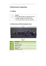
Page 26: ...8 8 8 2 A B C D E F 1 2 RS W S485 WIFI 22 15 7...
Page 27: ...8 3 8 3 3 P 1 MPPT PV T 23 MPPT PV 16 V1 PV2 MPP PT...
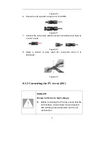
Page 28: ...MPP 8 3 1 100 V PT 2 17 M DC 23 MC4 MC4 24 PV MPP IP68 4 MPP 22 A V1 PT A DC PV2 MC4...
Page 29: ...1 2 3 4 5 7 25 17 18 19 7 8 9...
Page 30: ...6 7 8 2 6 2 9 9NM 26 20 2 0 1 22 23...
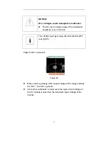
Page 31: ...8 3 3 P PV PV 27 V 110 27 00Vdc O OFF...
Page 32: ...PV PV PV 24 25 26 IP65 V 28 5 PV 6 PV IP68 OF FF 1 3 2...
Page 34: ...8 4 2 30 1 5 4 2 5...
Page 35: ...4 2 2 28 29 31 27 30 30 31 2 29...
Page 36: ...32 30...
Page 37: ...9 9 9 1 1 LED 1 1 LED1 Off On 33 LED 31 9 9 M MPPT...
Page 38: ...9 1 9 1 9 2 1 2 LED2 1 3 LED3 2 LCD Off On Off On LCD 34 10 1 32 0 1 L 30 LCD LCD LCD...
Page 41: ...F17 F18 F20 F25 F27 F28 F29 F30 F33 F36 F49 F51 F52 F62 F63 F65 F66 37 PV1 PV2 Boost AD ARM...
Page 44: ...10 2 2 WiF WiFi WiFi 38 RS48 i W 40 Web 5 USB 39 RS485 WiFi W bbox P PC WiFi PC...
Page 45: ...Wi Wifi ifi 41 40 W 41 Wifi Wifi Wifi...
Page 46: ...11 LED3 42 14 LCD...
Page 47: ...DC 14 C 43...
Page 48: ...12 12 12 12 13 12 1 2 3 F to 158 4 24 F 44 25 5 70...
Page 49: ...13 S 400 ST5KTL ST 756 5188 a b c d e T6KTL ST7 45 7KTL ST8K 5 KTL...
Page 51: ...Solar On Grid Inverter ST5KTL ST6KTL ST7KTL ST8KTL User Manual Version 2 0 EN...
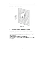
Page 76: ...24 Figure 12 7 5 Fixed the Inverter on the Wall Mount the inverter to the bracket Figure 13...


