background image


-27-

Parts List                                                                                               

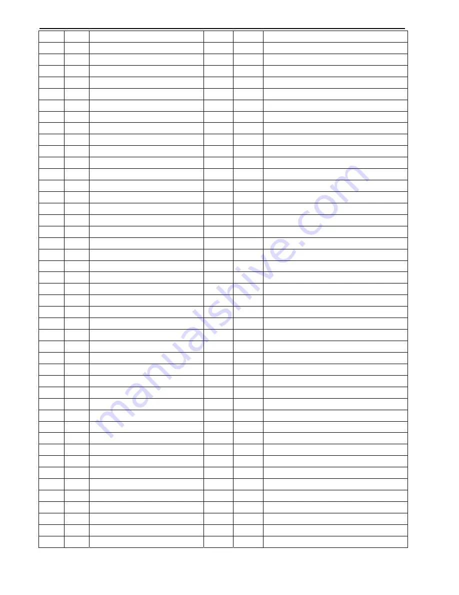
ITEM Q’TY PARTS   NAME 

ITEM

Q’TY PARTS   NAME 

Main Frame Assembly 

45 

M4x20L Flat Head Screw 

Console Tube 

46 

M8x38L Hex Head Screw( Carbon) 

Seat Post 

47 

M8x70L Carriage Bolt 

Seat Post Slider 

48 

TP5x32L Screw(Silver) 

Front Foot Tube 

49 

TP4x12L Screw 

Rear Foot Tube 

50 

TP4x16L Screw 

Belt Tension Bracket 

51 

M8x20L Hex Head Screw 

Mag Brake 

52 

TP5x15L Screw 

2.8x114mm Spring 

53 

M6x20L Hex Head Screw(Silver) 

10 

480J6 V-Belt 

54 

M8x15L Hex Head Screw 

11 

Generator   

55 

M8 Locknut (Silver) 

12 

M5x10mm Screw 

56 

M8x45L Hex Head Screw 

13 

Aluminum Pulley 

57 

M8x57L Hex Head Screw 

14 

Pulley Axle with Plate 

58 

M6 Hex Nut (Silver) 

15 

M20 Shaft Nut 

59 

M6 Locknut (Silver) 

16 

#6004-2RS Precise Bearing 

60 

M8 Locknut (thin) 

17 

#608-2RS Precise Bearing 

61 

M8 Locknut (thick) 

18 

Drive Cable (Tension Cable) 

62 

M8 Nut Cap 

19 

Aluminum Idler Pulley 

63 

3/8”x26mm Cap Nut 

20 1 

8x12.5x10L 

Spacer 

64  2 

8x18mm 

Curve 

Washer 

21 

1” Ball Plug 

65 

11 

8x19x1.0t Black Washer 

22 

Handlebar Sleeve 

66 

10x19x2.0t Black Washer 

23 1 

Seat 

Adjustment 

Knob(22L) 

67  1 

20x30x1.0t 

Washer(Silver) 

24 1 

Locking 

Knob 


68  1 

20x30x2.0t 

Washer(Silver) 

25 

Right Crank 

69 

R22 Retainer Ring 

26 

Left Crank 

70 

Adjustment Channel 

27 

M10XP1.25R Cap Nut 

71 

Seat 

28 

Crank Central Cap 

72 

Right Pedal 

29 1 

Magnet 

73  1 

Left 

Pedal 

30 

Hand Pulse with Wire 

74 

Right Pedal Strap 

31 

Monitor 

75 

Left Pedal Strap 

32 1 

Bottom 

Right 

Housing 

76  3 

8x19x1.0t 

Washer(Silver) 

33 

Handlebar Front Cover 

77 

Gear Box with Wire 

34 

Bottom Left Housing 

78 

Generator Supporting Metal Plate 

35 

Handlebar Rear Cover 

79 

Round Cover 

36 2 

Transportation 

Wheel 

80 

Controler Sensor Wire 

37 

Rear Foot Cap 

81 

Front Handlebar 

38 

40x 80 Inner Bushing 

82 

Control Board 

39 1 

38x45mm Right Inner Bushing(#1)

83 

Sensor Wire (with sensor) 

40 1 

38x45mm Left Inner Bushing(#2) 

84 1 

Extension 

Wire 

41 2 

38X45mm Rear Inner Bushing(#3)


42 

38x38mm End Cap 


43 

Plastic Inner Plug 


44 3 

Eyebolt 

6x40mm 


Summary of Contents for 400U-G

Page 1: ...400U G Upright Bike OWNER S MANUAL ...

Page 2: ...ontents Important Safety Information 3 Before You Start 4 Pre assembly Check List 5 Assembly Instruction 6 15 Console Overview 16 22 Monitoring Your Heart Rate 23 25 Exploded View 26 Parts List 27 2011 10 B31822TOB ...

Page 3: ...er be used while you are wet We recommend a mat be placed under the unit to protect floor or carpet and for easier cleaning 4 Wear comfortable good quality walking or running shoes and appropriate clothing Do not use the unit with bare feet sandals socks or stockings 5 Always examine your unit before using to ensure all parts are in working order 6 Allow the unit to fully stop before dismounting 7...

Page 4: ...medication consult your physician to see if the medication will affect your exercise heart rate If you have heart problems you are not active and or are over the age of 35 years do not use the pre set programs or start an exercise program without first contacting and receiving approval from your physician To avoid the risk of electrical shock always keep the console dry Do not spill liquids on the...

Page 5: ... 5 Pre assembly Check List Parts Bag Packing List ...

Page 6: ... 1 using Qty 4 47 Carriage Bolt Qty 4 65 Washer Qty 4 62 Nut Cap Make sure that the Front Foot Tube 5 with Transport Wheels 36 and Rear Foot Tube 6 with Foot Caps 37 are assembled to the Main Frame securely FIGURE 1 REMOVE ALL SECURITY TAPE AND WRAPPING BEFORE BEGINNING ...

Page 7: ...pull it backward to hold on at the same time slide the Seat Post 3 into Main Frame 1 last release Locking Knob 24 to spring into the hole of Seat Post and secured by turning it clockwise IMPORTANT Locking Knob 24 must be locked tightly into hole in Seat Post 3 before you sit on the seat FIGURE 2 ...

Page 8: ...e of Right Crank 25 Secure in place by turning it clockwise to tighten Note Right Pedal 72 is marked with an R Step 2 Thread the Left Pedal 73 into the hole of Left Crank 26 Secure in place by turning it counter clockwise to tighten Note Left Pedal 73 is marked with an L FIGURE 3 ...

Page 9: ...derside of Seat Step 2 a Turn Seat Adjustment Knob 23 counterclockwise to loosen b Pull Seat Adjustment Knob 23 backward at the same time insert Seat Post Slider 4 into Seat Post 3 to your desired position c Release the Seat Adjustment Knob 23 to spring into the hole of Seat Post Slider 4 and turn clockwise until tight to remove any looseness FIGURE 4 ...

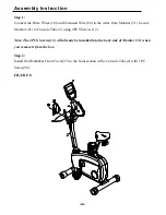
Page 10: ...Assembly Instruction FIGURE 5 Connect the Extension Wire 84 to the Controller Sensor Wire 80 Slide the Console Tube 2 onto the Main Frame 1 and secure using 5PCS Washers 65 5PCS Hex Head Screws 54 FIGURE 5 ...

Page 11: ... 1 Feed Hand Pulse Wires 30 into the top body hole of Console Tube 2 and up through the opening of Console Tube Step 2 Attach Pulse Handlebar 81 to Console Tube 2 using 3PCS Hex Screws 57 54 3PCS Washers 65 64 and 2PCS Locknuts 61 FIGURE 6 ...

Page 12: ...IGURE 7 1 The Monitor 31 is using 4PCS AA Rechargeable Battery 2 Please disassemble the battery box gently because there are connecting wires inside attach to Monitor 3 Last please read the Monitor instruction pages for details ...

Page 13: ... 13 Assembly Instruction FIGURE 8 Install the Handlebar Rear Cover 35 to the rear section of the Console Tube 2 with 1 PC Screw 50 ...

Page 14: ...m Monitor 31 Secure Monitor 31 to Console Tube 2 using 4PCS Screws 12 Note The 4PCS Screws 12 will already be installed into the back side of Monitor 31 when you remove it from the box Step 2 Install the Handlebar Front Cover 33 to the front section of the Console Tube 2 with 1 PC Screw 50 FIGURE 8 ...

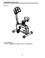
Page 15: ... 15 Assembly Instruction FIGURE 9 Congratulations You have completed the assembly of your new Upright Bike ...

Page 16: ...rkout time in minutes and seconds Your computer will automatically count up from 0 00 to 99 59 in one second intervals You can also program your computer to count down from a set value by using the UP and DOWN keys If you continue exercising once the time has reached 0 00 the computer will begin beeping and reset itself to the original time set letting you know your workout is done 2 DISTANCE Disp...

Page 17: ...he current data entry b At the stop mode by holding this key for over two seconds the user can reset all values to zero or default value c During setting the Clock press this key can accept the setting hour and setting minute 5 BODY FAT key Press the key to input your HEIGHT WEKGHT GENDER and AGE then to measure your body fat ratio 6 PULSE RECOVERY key Press the key to activate heart rate recovery...

Page 18: ...ur target DISTANCE Press ENTER key to confirm your desired DISTANCE 8 The CALORIES will flash and you can press UP or DOWN keys to setting your exercise CALORIES Press ENTER key to confirm your desired CALORIES 9 The PULSE will flash and then you can press UP or DOWN keys to set your exercise PULSE Press ENTER key to confirm your desired Pulse 10 Press the START STOP key to begin exercise Heart Ra...

Page 19: ...vided according to the FAT calculated Type1 BODY FAT 27 Type2 27 BODY FAT 20 Type3 BODY FAT 20 The computer will show the test results of FAT PERCENT BMI and BMR Operations 1 Use UP DOWN keys to select the BODY FAT P24 program 2 Press the ENTER key to enter your workout program 3 The HEIGHT will flash and you can press UP or DOWN keys to set your HEIGHT Press ENTER key to confirm your HEIGHT The d...

Page 20: ...ark are blank and the output signals are cut off also E2 ERROR 2 When the monitor read the memory data if the I D code is not correct or the memory IC damages then the monitor will show E2 immediately at power on E3 ERROR 3 After 4 seconds by start mode the computer detects the faulty motor did not leave the zero point then the LCD bar displays E3 LCD Workout Graphics PRESET PROGRAM PROFILES PROGR...

Page 21: ... 21 PROGRAM 15 USER 2 PROGRAM 16 USER 3 PROGRAM 17 USER 4 HEART RATE PROGRAM PROFILES PROGRAM 18 55 H R C PROGRAM 19 65 H R C PROGRAM 20 75 H R C PROGRAM 21 85 H R C PROGRAM 22 TARGET H R C ...

Page 22: ...AM 24 BODY FAT STOP MODE BODY FAT START MODE One of the Following Six Profiles Will Display Automatically after Measuring Your BODY FAT Workout Time 40 minutes Workout Time 40 minutes Workout time 20 minutes Workout Time 40 minutes Workout Time 40 minutes Workout time 20 minutes ...

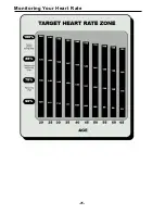
Page 23: ...or against your wrist over the main artery After finding your pulse count the number of beats in 10 seconds Multiply the number of beats by six to determine your pulse rate per minute We recommend taking your heart rate at these times at rest after warming up during your workout and two minutes into your cool down to accurately track your progress as it relates to better fitness During your first ...

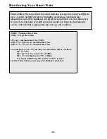
Page 24: ...gh end or 75 of MHZ 30 year old THR Target Heart Rate would be 114 142 See Heart Rate Table on next page for additional calculations Fitness Safety The target heart rate chart indicates average rate zones for different ages A variety of different factors including medication emotional state temperature and other conditions can affect the target heart rate zone that is best for you Your physician o...

Page 25: ... 25 Monitoring Your Heart Rate ...

Page 26: ... 26 Exploded View ...

Page 27: ...y 63 2 3 8 x26mm Cap Nut 20 1 8x12 5x10L Spacer 64 2 8x18mm Curve Washer 21 2 1 Ball Plug 65 11 8x19x1 0t Black Washer 22 2 Handlebar Sleeve 66 2 10x19x2 0t Black Washer 23 1 Seat Adjustment Knob 22L 67 1 20x30x1 0t Washer Silver 24 1 Locking Knob 68 1 20x30x2 0t Washer Silver 25 1 Right Crank 69 1 R22 Retainer Ring 26 1 Left Crank 70 2 Adjustment Channel 27 2 M10XP1 25R Cap Nut 71 1 Seat 28 2 Cra...

Reviews: