background image


21 


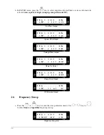
F R  Q :  1  .  0  0  0  0      K H z 

  A  M   E  X  T  E  R  N      S  B  3   


AM On, External Source 


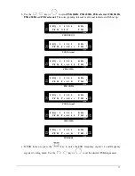
F  R  Q :  1  .  0  0  0  0      K H z   
  P  WH    O F  F          S  B  4   


Square Wave Pulse Width Adjustment Off 


F  R  Q :  1  .  0  0  0  0      K H z   
  P  WH    P  o  s          S  B  4   


Square Wave Pulse Width Adjustment On and Output Positive Pulse 


F  R  Q :  1  .  0  0  0  0      K H z   
  P  WH    N  e  g          S  B  4   


Square Wave Pulse Width Adjustment On and Output Negative Pulse 


F  R  Q :  1  .  0  0  0  0      K H z   
  P  WH    B  o  t  h  O n    S  B  4   


Square Wave Pulse Width Adjustment On and Output Positive and Negative Pulse 


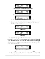
F  R  Q :  1  .  0  0  0  0      K H z   
  P  WH    P  u  l  s  e      S  B  4   


Square Wave Pulse Width Adjustment On and Output Pulse 


Note  : The  square  wave  pulse  width  adjustment  on/off  selection  will  show  up  in  the  sub 

function only if the output select to square wave. If the pulse width adjustment is on, 

the pulse width indicator will show up. 


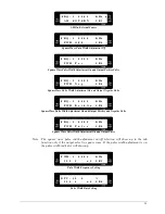
P  WH :  1  .  0  0  0  0      K H z   
  5  0  0  .  0        u  S    S  B  5   


Pulse Width Frequency Setting 


D  T  Y  :  5  0  .  0          %     
  5  0  0  .  0        u  S    S  B  6   


Pulse Width Duty Setting 


Summary of Contents for FG 700F Series

Page 1: ...Operating Manual FG 700S F Series Direct Digital Synthesis Function Generator...

Page 2: ......

Page 3: ...hat the product is set to match the available line voltage is installed SAFETY SYMBOLS Caution risk of electric shock Earth ground terminal Equipment protected throughout by double insulation or reinf...

Page 4: ...arranty does not cover finish or appearance items nor does it cover items damaged in shipment to MOTECH for repair or calibration To receive service under this warranty you must include proof of purch...

Page 5: ...ng Screen 8 2 3 Setting Group Name 9 2 4 Adjust Frequency 9 2 5 Select Waveform 9 2 6 Frequency Sweep 10 2 7 Output Attenuation 13 2 8 Rotary Frequency Step Setting 13 2 9 Amplitude Offset and Square...

Page 6: ......

Page 7: ...K modulation gives you the ability to generate such waveform for experiment or communication purpose The FG 700F series comes with AM FM module and frequency counter to make the function of this produ...

Page 8: ...Square Wave Pulse Width Adjustment On Off Indicator 4 Output Offset On Off Indicator 5 Output Amplitude Attenuation Range Indicator 6 External Internal indicator of Trigger Gate or PSK FSK 7 Rotary wi...

Page 9: ...10mV 0 1V 9 99V 1mV 10mV 99mV 0 1mV 1mV 9 9 mV 0 01mV 0 90mV 0 99mV Depend on Attenuation f Amplitude Accuracy Typical 1 test at 1KHz 9Vp p sine 50 load g Output Attenuation 0 20 40 and 60 db h FUNC_O...

Page 10: ...Power Source AC 115V 230V 10 50Hz 60Hz b Temperature 0 C 40 C Operation 20 C 70 C Storage c Relative Humidity up to 80 d Dimension 235mm W 95mm H 280mm D e Weight 3Kg f Accessories AC power cord 1 Op...

Page 11: ...down and up down s Sync Output Frequency range 100mHz 10M 20MHz Output level low level 0 6V 50 high level 1V 50 Output impedance 50 Modulation Characteristics a FM Modulation Sine Suqare or Triangle...

Page 12: ...ptional TCXO Time Base Available f Input Attenuation 0db 20db g Sensitivity 4Hz 50MHz 20dbm 50 typical 50MHz 80MHz 10dbm 50 typical 80MHz 100MHz 5dbm 50 typical General Characteristics a Power Source...

Page 13: ...equency step menu to select and set the frequency step function Frequency Step Attenuation Key Counter LPF Key FG700F Series a Enter the attenuation menu to change the output attenuation b Enter the f...

Page 14: ...Knob FG700S F Series a Adjust the DC level if the function output is set to DC b Adjust the offset level if the output offset is on Pulse Width Adjustment Knob FG700S F Series a Adjust the amplitude o...

Page 15: ...er is set currently For example SW1 sets the sweep mode of linear or logarithm SW2 sets the type of sweep and SW3 sets the sweep start frequency etc 2 4 Adjust Frequency a When the cursor does not app...

Page 16: ...Q U Square Wave Output F R Q 1 0 0 0 0 K H z A M P 1 0 0 V T R I Triangle Wave Output F R Q 1 0 0 0 0 K H z A M P 1 0 0 V R U P Ramp Up Output F R Q 1 0 0 0 0 K H z A M P 1 0 0 V R D W Ramp Down Outp...

Page 17: ...ep stop frequency and sweep step frequency or ratio Use the key or to select the desired sweep type or frequencies L I N 4 0 0 0 2 K H z T S W U p S W2 Type of Sweep Up L I N 4 0 0 0 2 K H z T S W U p...

Page 18: ...Ratio Actual F n 1 n 1010 025Hz 1005Hz 1 005 F Ratio Actual F 1 n 2 n 5Hz 1015 07512 1010 025Hz 1 005 F Ratio Actual F 2 n 3 n Note The maximum value of the logarithm sweep step ratio setting is 10 0...

Page 19: ...40 and 60 dB The corresponding amplitude indicator will show the current output attenuation setting F R Q 1 0 0 0 0 K H z A T N 0 D B A T 1 0dB Output Attenuation F R Q 1 0 0 0 0 K H z A T N 2 0 D B A...

Page 20: ...z F r q S t e p S e t A T 3 Note Once the frequency step is set to manual the output frequency can be controlled by the key or 2 9 Amplitude Offset and Square Wave Pulse Width Display a In FG700S ser...

Page 21: ...over if the pulse width is under or above the following values in FG708S Frequency Range Display Shows 0 1Hz 5 99999MHz 6 00000MHz 8 00000MHz BELOW 18 34 OVER 81 75 g To adjust the pulse width in FG7...

Page 22: ...or external indicator will show up F R Q 1 0 0 0 0 K H z T R G O F F T M 2 Trigger Gate Off F R Q 1 0 0 0 0 K H z E X T T R G T M 2 External Trigger F R Q 1 0 0 0 0 K H z R O T P T R G T M 2 Rotary P...

Page 23: ...M 3 FSK External F R Q 1 0 0 0 0 K H z P F M F s k 4 0 0 T M 3 FSK 400Hz F R Q 1 0 0 0 0 K H z P F M F s k 1 K T M 3 FSK 1KHz F R Q 1 0 0 0 0 K H z P F M P s k E x t T M 3 PSK External F R Q 1 0 0 0...

Page 24: ...generator or 12 0000MHz d If PSK turns on press the key to enter the PSK phase setting menu Use the key or to set the desired PSK phase D E G 9 0 0 0 P S K P h s S e t T M 6 PSK Phase Setting 2 12 Su...

Page 25: ...tment is on the pulse width indicator will show up F R Q 1 0 0 0 0 K H z O F F S E T O F F S B 3 Output Offset Off F R Q 1 0 0 0 0 K H z O F F S E T O N S B 3 Output Offset On Note If the output offse...

Page 26: ...Off F R Q 1 0 0 0 0 K H z S Y N O N S B 1 Sync Output On F R Q 1 0 0 0 0 K H z O F F S E T O F F S B 2 Output Offset Off F R Q 1 0 0 0 0 K H z O F F S E T O N S B 2 Output Offset On F R Q 1 0 0 0 0 K...

Page 27: ...F R Q 1 0 0 0 0 K H z P WH B o t h O n S B 4 Square Wave Pulse Width Adjustment On and Output Positive and Negative Pulse F R Q 1 0 0 0 0 K H z P WH P u l s e S B 4 Square Wave Pulse Width Adjustment...

Page 28: ...mportant for the best performance Because the function generator output is a wideband signal every connecting path including the transmitter or receiver must be impedance matched to 50 in order to avo...

Page 29: ...gnal Output In general the function generator output is 20Vp p in open circuit and the output current is limited to less than 100mA For high voltage and high current output in special applications the...

Page 30: ...ZOMG 700ME 1B...
Reviews: