background image


1.   

GENERAL INFORMATION 

1.1 

Introduction 


This  section  contains  a  general  description  of  your  power  supply  as  well  as  its  performance 
specifications. Information about options and accessories are also provided. 
The TPS-3025 series has been designed and tested according to EN-61010-1, Safety requirement for 
Electronic Measuring Apparatus. 
 

1.2 

Safety Considerations 

 
SAFETY PRECAUTIONS 
 

SAFETY NOTES 
The  following  general  safety  precautions  must  be  observed  during  all  phases  of  operation,  service, 
and  repair  of  this  instrument.  Failure  to  comply  with  these  precautions  or  with  specific  warnings 
elsewhere  in  this  manual  violates  safety  standards  of  design,  manufacture,  and  intended  use  of  the 
instrument.  The


manufacturer  assumes  no  liability  for  the  customer’s  failure  to  comply  with  these 

requirements. 


BEFORE APPLYING POWER         

Verify that the power supply is set to match the available line voltage and the correct fuse is installed. 


GROUND THE INSTRUMENT 

This  product  is  provided  with  a  protective  earth  terminal.  To  minimize  shock  hazard,  the  instrument 
chassis and cabinet must be connected to an electrical ground. The instrument must be connected to 
the  AC  power  supply  mains  through  a  three-conductor  power  cable,  with  the  third  wire  firmly 
connected to an electrical ground (safety ground) at the power outlet. For instruments designed to be 
hard-wired to the AC power lines (supply mains), connect the protective earth terminal to a protective 
conductor  before  any  other  connection  is  made.  Any  interruption  of  the  protective  (grounding) 
conductor  or  disconnection  of  the  protective  earth  terminal  will  cause  a  potential  shock  hazard  that 
could result in personal injury. If the instrument is to be energized via an external autotransformer for 
voltage  reduction,  be  certain  that  the  autotransformer  common  terminal  is  connected  to  the  neutral 
(earthed pole) of the AC power lines (supply mains). 
The  RS232  (option)  Ground  is  connected  with  chassis  ground,  and  therefore  the  operator  must  take 
care if the computer is also connected with other measuring devices prevent a short cut. 
 

FUSES 

Only fuses with the required rated current, voltage, and specified type (normal blow, time delay, etc.) 
should  be  used.  Do  not  use  repaired  fuses  or  shout  circuited  fuseholders.  To  do  so  could  cause  a 
shock or fire hazard. 
 

DO NOT OPERATE IN AN EXPLOSIVE ATMOSPHERE 

Do not operate the instrument in the presence of flammable gases or fumes. 

 
KEEP AWAY FROM LIVE CIRCUITS 

Operating  personnel  must  not  remove  instrument  covers.  Component  replacement  and  internal 
adjustments  must  be  made  by  qualified  service  personnel.  Do  not  replace  components  with  power 
cable connected. 

!


Summary of Contents for LPS 305

Page 1: ...LPS 305 Linear Programmable Power Supply User s Manual ...

Page 2: ...e fuse 5 3 GETTING STARTED 6 3 1 Front panel controls and output terminals 6 3 2 LCD display message 8 REFER TO THE FIGURE B 8 3 3 Rear panel 9 4 OPERATION 10 4 1 Initial conditions 10 4 2 Control of output functions 10 4 3 Enabling Disabling the output 11 4 4 Overload protection of 5V or 3 3V output 11 5 CALIBRATION 12 6 USER MAINTENANCE SERVICE 15 6 1 Fuse Replacement 15 6 2 In Case of Difficult...

Page 3: ......

Page 4: ...h the third wire firmly connected to an electrical ground safety ground at the power outlet For instruments designed to be hard wired to the AC power lines supply mains connect the protective earth terminal to a protective conductor before any other connection is made Any interruption of the protective grounding conductor or disconnection of the protective earth terminal will cause a potential sho...

Page 5: ...ld result in personal injury Do not proceed beyond a WARNING sign until the indicated conditions are fully understood and met CAUTION The CAUTION sign denotes a hazard It calls attention to a procedure practice or the like which if not correctly performed or adhered to could result in damage to or destruction of part or all of the product Do not proceed beyond a CAUTION sign until the indicated co...

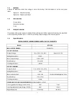
Page 6: ...und 1 6 Specifications TRIPLE OUTPUT LINEAR POWER SUPPLY UP TO 165 WATTS Model LPS 305 MAX OUTPUT POWER 165 WATTS OUTPUT VOLTAGE Output Voltage 0 to 30V 0 to 30V Fixed 3 3V 5V Setting Resolution 10mV Max output voltage 32V 32V Dual tracking 0 to 30V Tracking deviation 20mV OUTPUT CURRENT Output Current 0 to 2 5A 0 to 2 5A 3A Setting Resolution 1mA Max output current 3A 3A Current limited approx 3 ...

Page 7: ... rdg 2 digits Current Accuracy 0 5 of rdg 5 digits Common Mode Voltage 240Vdc Temperature ranges Operating 0 to 40 less than 80 RH Storage 40 to 70 less than 80 RH Dimensions W H L 8 4 5 2 15 7 Weight Approx 18 lbs Cooling Fan Cooled Power Source AC 115V 10 OR 230V 10 47 to 63Hz Current Consumption 2 88A AC 115V or 1 48A AC 230V Fuse Rating 5AT 250V for AC 115V 2 5AT 250V for AC 230V Options RS 23...

Page 8: ...an operate without sacrificed performance within the temperature range of 0 to 40 measured at the fan intake The fan located at the rear of the unit cools the supply by drawing air in through the openings on the sides and exhausting it through the opening on the rear panel Since the power supply is fan cooled it must be installed in a location that allows sufficient clearance of 1 inch 25mm is req...

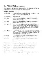
Page 9: ...respectively If the key is pressed and held it will continually increase the setting until it is released Numeric entry key for number nine 6 down output control key used to decrease the voltage settings when the supply is in the CV mode or the current settings when the supply is in the CC mode by 10mV or 1mA per step If the key is pressed and held it will continually decrease the setting until it...

Page 10: ...y which toggles the output on or off simultaneously 19 output terminal RED This terminal is used to output 30V 2 5A with respect to the COM1 terminal 20 COM1 Terminal BLACK The common terminal which is used for 30V 2 5A output 21 output Terminal WHITE This terminal is used to output 30V 2 5A with respect to the COM1 terminal 22 GDN Terminal GREEN This ground earth terminal is connected to the main...

Page 11: ...16 15 17 18 2 24 23 11 O I POWER ON OFF 5V 3 3V COM1 0 4 TRACK 1 2 5 3 BEEP 6 7 3 4 8 9 6 5 10 OUTPUT VSET VSET 7 8 ISET ISET 9 240 Vc MAX FIGURE A 3 2 LCD display message REFER TO THE FIGURE B FIGURE B ALL OUTPUT OFF CV CV INDEP 5V 20 00V 15 00V CC CC TRACK 3 3V 3 4 1 2 ...

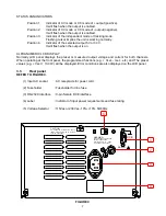
Page 12: ...age and current for both channels When operating at the front panel the programmed functions e g Vset Iset etc and The preset values e g Vset 10 00V will be displayed Error conditions are also displayed on the LCD panel 3 3 Rear panel REFER TO FIGURE C 1 Input AC socket AC receptacle for power cord 2 Fuseholder Fuseholder for line fuse 3 RS 232C interface 9 pin female DCE interface 4 Label Indicat...

Page 13: ...a mistake Pressing the ENTER key will enter the values displayed for the function indicated initiate that function initiate that function and return the display to the output off mode or to the metering mode output on in which the measured numbers will result in retention of the previous values and return to the previous mode You can also return to the previous mode at anytime by pressing the CLEA...

Page 14: ... output disabled by the output on off key will be have as if it were programmed to zero volts 4 4 Overload protection of 5V or 3 3V output When the 5V or 3 3V output current is approximately 20 percent above the current output rating or if the output is shorted the overload protection circuit will be activated and the output will be disabled To reset the output first clear the condition that cause...

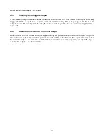
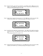
Page 15: ... and key in the measured value i e if the DMM shows 9 487V then key in 9 487 followed by the ENTER key The following message will then appear on the LCD Step 3 Repeat step 2 Key in the measured value i e if the DMM shows 29 798V then key in 29 798 followed by the ENTER key The following message will then appear on the LCD V Lo 09 487 CV CV INDEP 5V ADC GET 01036 CC CC TRACK 3 3V V Hi 29 798 CV CV ...

Page 16: ...on the LCD Step 6 Measure the DC voltage from output terminals and COM1 with the DMM and keyin the measured value i e if the DMM shows 9 624V then keyin 9 624 followed by the ENTER key The following message will then appear on the Step 7 Repeat step 6 Keyin the measured value i e if the DMM shows 30 036V then keyin 30 036 followed by the ENTER key The following message will then appear on the LCD ...

Page 17: ...r on the LCD Step 9 Repeat step 8 Keyin the measured value i e if the DMM shows 2 418A then keyin 2 418 followed by the ENTER key The following message will then appear on the LCD ADC GET 00200 CV CV INDEP 5V I Lo 0 624 CC CC TRACK 3 3V ADC GET 02503 CV CV INDEP 5V I Hi 2 418 CC CC TRACK 3 3V MOTECH LPS 305 CV CV INDEP 5V Version 1 17 CC CC TRACK 3 3V ALL OUTPUT OFF CV CV INDEP 5V 10 00V 10 00V CC...

Page 18: ...2 Remove and test the fuse The power supply will not function with an open fuse If the preceding two steps fail to resolve the problem NOTE ATTEMPTED REPAIR MODIFICATIONS OR TAMPERING BY UNAUTHORIZED PERSONNEL WILL VOID THE WARRANTY 6 3 If the ERROR 2 shows on LCD If the ERROR 2 shows on LCD the calibration data in the EEPROM has been erased The power supply needs to be recalibrated Please process...

Page 19: ... Use async framing 8 data bits no parity bit 1 stop bit 3 Bit rate 2400bps 4 Every command string is terminated by CR or LF or BOTH carriage return 5 There is one command allowable in a command string 6 A command string enters before OK prompt will be reject no function 7 STATUS operation explanation After a TPT 3025 accept A STATUS command it will display a decimal number in ASCLL Convert this de...

Page 20: ...17 Bit 9 0 beeper function off 1 beeper function on Bit 10 0 CC output compensated off 1 CC output compensated on ...

Page 21: ......

Page 22: ...ZOM 305MI 1B ...

Reviews: