Installation Manual
5
MOTECH Industries, Inc., -
Tainan Science Park ı No.2, Dashun 9th Rd., Xinshi Dist., Tainan City, 74145, Taiwan
Tel: +886-6-5050789 | E-mail:
Page:
9.3 In solar battery-charging arrays, blocking diodes are required to prevent the solar module from discharging the battery
bank at night. Motech modules do not include blocking diodes. It is recommended that a charge controller be used to
prevent system batteries from being overcharged during the day and discharged at night.
10. Equipment Ground
In order to use safety and avoid damage to components by lightning and static electricity, all solar photovoltaic module borders
and mounting brackets must be properly grounded in accordance with relevant national electrical regulations. Grounding wires
can be copper, copper alloys, or other materials that can be used as conductors and comply with electrical regulations. When
grounding, the grounding device must be fully in contact with the aluminum alloy inside the aluminium frame, to penetrate the
oxide film on the border surface, each grounding hole on the frame of the assembly is marked. All grounding devices must
comply with relevant national regulations and usage requirements.
11. Module Mounting
11.1 Please do not artificial gathered light on the surface of the module.
11.2 The ambient temperature of the module installation is recommended to be between -20°C and +46°C Celsius. Maximum
operating temperature range -40°C ° Celsius to +85°C.
11.3 The minimum safe distance between the module and the module is recommended for 1 cm when the solar panel is
installed.
11.4 To ensure proper module mounting and a robust mounting system that allows the modulet to withstand all predetermined
loads, the bracket installer must provide its warranty.
11.5 The maximum power is 315W. It is recommended that the number of series not exceed 28 and the maximum number of
parallels should not exceed 1.
11.6 Each module has several drain holes to prevent water from accumulating in the aluminum frame. When installing, keep
the drain holes unobstructed. The drain holes should not be blocked by the fixture to avoid water or ice in the frame after
the cover, which may cause the frame to fail.
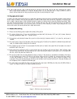
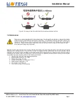
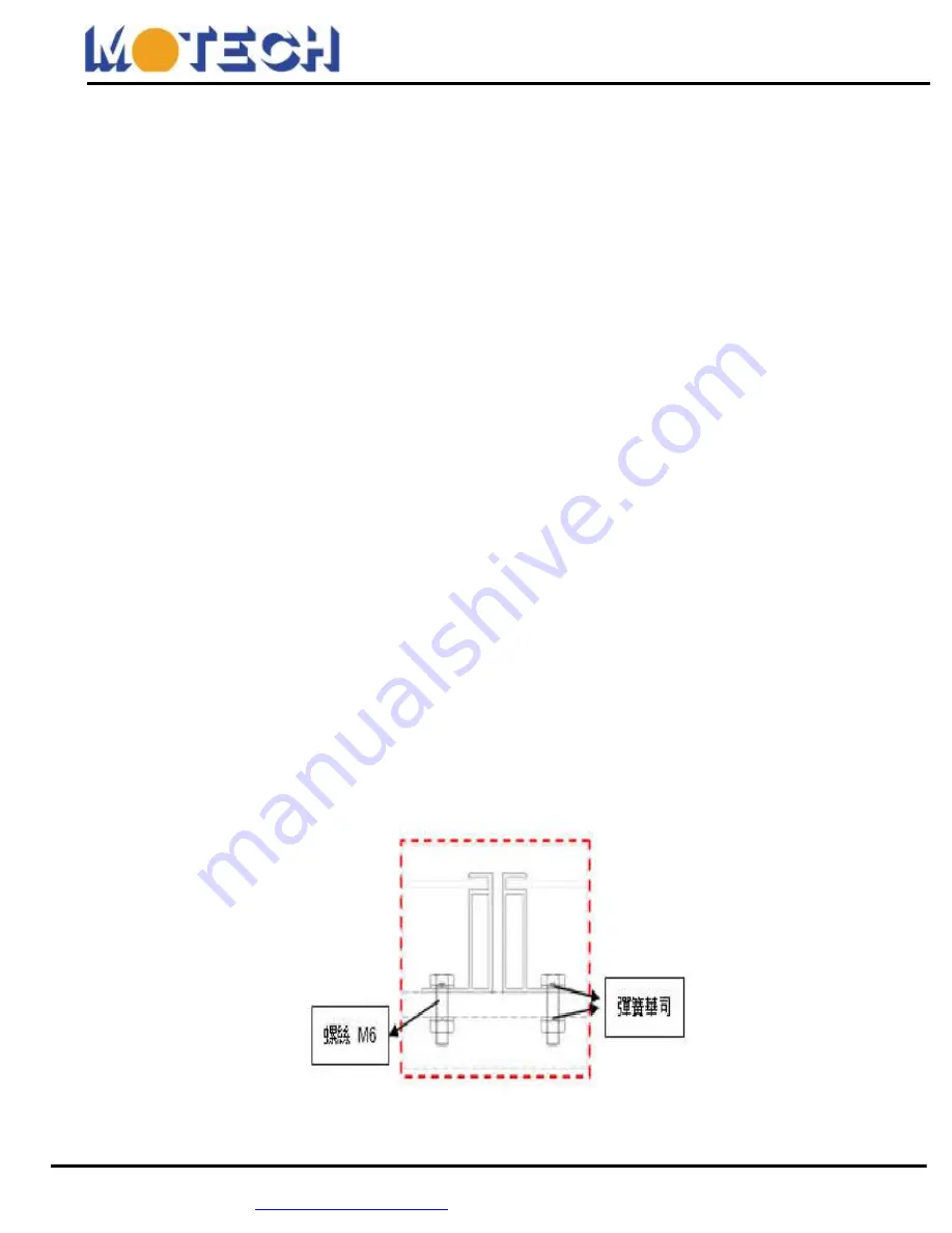
11.7 The module is fixed to the mounting bracket as shown in Figure 2. The module can be bolted to the bracket or the fixture
can be mounted using a clamp. If the fixture is used to secure the module to a bracket, the recommended fixture width is
≥
38mm and thickness is
≥
4.5mm. It is required that the fixture can not touch the glass or deform the frame of the
component. The contact surface between the fixture and the frame must be smooth and smooth, otherwise the frame will
be damaged and the components will be damaged.
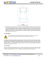
11.8 The solar module has passed the static mechanical test with a back load of 2400Pa and a front load of 5400Pa. Refer to
Figure 1 and Figure 2 below for the fixture installation method:
Figure 1. White iron screw mounting hole