background image

- 32 -

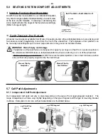
+10 degrees

-10 degrees

A.

(

standard set-up)

B.

(

fully raised)

C.

(

fully lowered)

tilt backcane installed at 

95

o

(standard configuration)

rotate the cam upward to
lower the armrest angle

(parallel to seat frame)

Note:

above images are shown with

the lever lock handle (optional)

Standard

Catilever Armrest Set-Up

Lowered

Catilever Armrest Set-Up

2B

2C

C

ANTILEVER

R

ECLINE

A

RMRESTS

Range of Adjustment

Armrest Angle Adjustment: 

(...cont’d)

5.0   

5.0   

SEATING SYSTEM COMFORT ADJUSTMENTS

SEATING SYSTEM COMFORT ADJUSTMENTS

Summary of Contents for F Series

Page 1: ...safety maintenance and operating information specific to the operation of our Motion Concepts Power Positioning System This Manual MUST be given to the user of the product BEFORE using this product please read through the instructions carefully and save for future reference ...

Page 2: ......
Page 3: ... partly or completely without previous written consent from Motion Concepts or its statutory representatives This owner s manual is compiled from the latest specifications and product information available at the time of publication We reserve the right to make any necessary as they become necessary Any changes made to our products may cause slight variations between the illustrations and explanat...

Page 4: ...ng System using a TRX Switch 3 4 Configuring the Seat Controls Direct Mode vs Toggle Mode 3 5 Power Positioning Functions 3 5 1 Standard F Series Positioning Functions 3 5 2 Additional F Series Positioning Options 3 6 Wheelchair Drive Controls 3 7 Operating via Specialty Controls 4 0 ELECTRONICS 4 1 Seat Motor Control Boxes 4 1 1 M Series Control Boxes 4 2 Wiring Harnesses 4 3 Safety Lockout and L...

Page 5: ...8 Back Adjustments 5 8 1 Back Angle Adjustments for Tilt Only Systems 5 8 2 Height Adjustments for Tilt Only Systems 5 9 Lateral Trunk Support Adjustments 5 9 1 Maxx Lateral Trunk Support 5 10 Headrests 5 10 1 Basic Headrest Set Up and Installation 5 10 2 Adjustable Headrest Set Up and Installation 5 11 Postural Belts 5 11 1 Types of Postural Bolts 5 11 2 Adjusting the Postural Belt Correctly 6 0 ...

Page 6: ...ionals has given us an understanding of the challenges that you may confront and has enabled us to design systems that will help to meet your individual positioning needs We are confident that you will be delighted with your new positioning system and as you grow or your needs change your new seating system will be able to grow and change with you Motion Concepts or their statutory representatives...

Page 7: ...r or damage to the product BURN HAZARD This symbol warns you of potential burns e g leaking battery acid Always follow the instructions to avoid injury to the user or damage to the product IMPORTANT Important information to remember when operating your Motion Concepts power positioning system NOTE This symbol identifies general information which is intended to simplify working with your product an...

Page 8: ...ship for a period of five 5 years Electronic components are warranted to be free from defects in material and workmanship for a period of eighteen 18 months If during the warranty period any component is determined at the sole discretion of Motion Concepts to be defective such component will be repaired or replaced at the option of Motion Concepts The sole obligation of Motion Concepts under this ...

Page 9: ...ntified by a unique serial number which allows us to trace the production history of the system and better equips us to address any service issues that may occur over the lifetime of the product The serial number identification plate for our F Series power positioning systems is located at the rear right outside corner of the seat frame module as indicated in the image below ...

Page 10: ...NFORMATION READ ALL SAFETY INFORMATION THOROUGHLY BEFORE OPERATION IMPORTANT Do not ignore unanswered questions You have the right to understand the product and all aspects of its operation If necessary please contact your Motion Concepts representative for information regarding any questions or concerns expressed NOTE The most important link in the delivery chain is you the end user You must be s...

Page 11: ...lted or reclined position When a system is fully tilted or reclined the front wheels of the powerbase should never come off the ground If this occurs please contact your authorised Motion Concepts Dealer Representative immediately to resolve the issue 2 0 2 0 SAFETY INFORMATION SAFETY INFORMATION 6 Recommended Maximum Incline Angle Ascending and Descending WARNING WHEN TRAVELLING ON INCLINES Any a...

Page 12: ...r power positioning system MUST match original Motion Concepts parts ALWAYS provide the wheelchair serial number to assist in ordering the correct replacement parts see section 1 4 GENERAL SAFETY HANDLING WARNINGS IMPORTANT Motion Concepts disclaims all responsibility and liability for any personal injury or damage to property that occurs as a result of improper or unsafe use of the power position...

Page 13: ...um recommended drive lockout DLO limit refer to Section 4 3 Safety Lockouts Limit Switches Never allow your Motion Concepts power positioning system to be used as a tie down point in a vehicle Use only the designated anchoring points on the power wheelchair see Section 2 8 1 Never allow your wheelchair to be lifted by any part of the Motion Concepts power positioning system Never extend your arms ...

Page 14: ...account the weight of the individual components especially the batteries Be sure at all times to adopt the correct lifting posture and ask for assistance if necessary WARNING Danger of injury by moving parts To avoid personal injury and injury to other individuals from moving wheelchair parts such as wheels power legrests and or tilt or elevate modules always be aware of your surroundings especial...

Page 15: ...mitation of the wheelchair is 300 lbs and additional items equal 25 lbs subtract 25 lbs from 300 lbs This means the maximum weight limitation of the user is 275 lbs WARNING Danger of injury if maximum permissible load is exceeded Do not exceed the maximum permissible load weight capacity of the power positioning system or the wheelchair base The wheelchair is only designed for use by a single occu...

Page 16: ...g system are designed and tested to meet all necessary safety standards WARNING The wiring harnesses cables are not to be modified in any way following the installation of our Motion Concepts power positioning system If installed on previously used product the existing OEM harnesses on the wheelchair should be examined for damage wear and replaced if necessary Please consult the wheelchair base ma...

Page 17: ...ly secured If you are unable to fasten your electric wheelchair securely in a transport vehicle we recommend that you do not transport it Before transporting your wheelchair make sure the motors are engaged and that the wheelchair power is switched off We strongly recommend securing the wheelchair to the floor of the transporting vehicle The wheelchair should always be anchored facing in the trans...

Page 18: ...wer base manufacturer In most instances the power positioning functions available on your Motion Concepts seating system may be programmed to be operated by means of the joystick control In order to access operate the motor functions via the joystick the joystick must be switched from Drive Mode to the Power Positioning Mode This is typically accomplished via a Mode Switch on the joystick The joys...

Page 19: ...n additional quarter sized single switch option as shown Two buttons are required to operate a seat function in Direct mode and one button is required to operate a function in Toggle mode LED Dual Quad Single Dual Toggle w LED indicator The dual toggle switch is capable of operating two functions in Direct mode and four functions in Toggle mode 4 Way Toggle w LED indicator The 4 way toggle switch ...

Page 20: ...tilt function on a power positioning system Table B Using the JOYSTICK to control the tilt function Direct Mode Pull the joystick control backward to tilt the seat back Push the joystick forward to tilt the seat forward Toggle Mode Push the joystick control forward to tilt the seat back Release the joystick pause for 1 2 seconds and push forward again on the joystick to tilt the seat forward This ...

Page 21: ...owing configurations Individual legrests operate independently Combined legrests operate in unison or Synchronized the legrest is sychronized to function together with recline 3 5 Power Positioning Functions Our modular seating systems are designed to provide dealers and therapists with the ultimate in versatility flexibility and adjustability Our modular systems can be readily adapted from base t...

Page 22: ...on via the powerbase joystick Joysticks can vary greatly in their features and functional capabilities For detailed instructions on how to operate your specific joystick please be certain to read the Power Base Joystick Owners Manual provided separately by the base manufacturer The following is intended only as a basic overview of a typical wheelchair drive control system In order to drive your wh...

Page 23: ...res and functions may be adjusted by the user and or attendant following delivery to ensure your seating system is programmed correctly and safely we strongly recommend that any programming changes to the electronics only be peformed by a qualified techincian The control boxes for the M Series electronics are designed for maximum programmability and function and their compact design occupies minim...

Page 24: ...gh and operate the desired motor functions on the power positioning system w Motor Speed Control The remote allows the individual actuator speeds to be adjusted set independently for both Forward and Reverse directions w Configuring Switches Joystick Functions The installed operator switch and or joystick ASM can be reconfigured to operate any desired motor function in either toggle or direct mode...

Page 25: ...kout switches may be required for more complicated specialized seating systems For information on limits lockouts that are not identified in this manual please contact our Technical Service Department for assistance WARNING Following any limit or lockout adjustments always test the seating system over the full range of motion i e tilt recline elevate to verify the revised set up is functioning pro...

Page 26: ...Lockout DLO or Elevate Reduced Drive Speed Limit home position Front Important Ensure base is on a level surface when adjusting settings 1 2 elevated T R E Drive Lockout Reduce Speed Drive 2 elevated Elevate Only DLO NOTE To regain full drive function of the wheelchair return the seat angle to a more upright position when Tilt Recline DLO is activated or lower the seat to its home position when El...

Page 27: ...5 Tilt Recline Recline Only Max Tilt Recline Limit 168 WARNING When establishing the max tilt limit always consider the size and location of any personal gear that may be carried on the wheelchair as it could cause interference between the backrest and the wheelchair base when fully tilted reclined and damage the actuator and or wheelchair 45 Max Scissor Lift Tilt Limit 4 3 4 Elevating Seat Lockou...

Page 28: ... is a programmable limit switch that utilizes a separate angle sensor mounted to the seating system There are 2 models of tipsy sensors available depending on the type of electronics installed on the PPS The M11 R Tipsy sensor is designed for use with our multi function Helix Series electronics and the M11 R5 Tipsy sensor is utilized with our M Series M600 M200 M136 electronics in combination with...

Page 29: ... vary depending on the base electronics and the type of wheelchair base The following images are provided for reference only Motion Concepts offers a wide range of positioning features options and we are constantly coming up with new innovative products to address the needs of our customers The following information is provided as a reference for our typical system configurations The components ac...

Page 30: ...er Lever Lock 5 2 1 Basic Tilt Armrest Adjustments The basic tilt style armest has a telescoping upper armrest to allow height adjustments in 1 2 13mm increments To adjust height Depress the detent pin at the front of the armrest and slide the upper armrest and armpad up or down as needed to the desired height 1 Note the detent pin must be engaged in one of the preset adjustment holes to lock the ...

Page 31: ...ustment INSIDE VIEW main bolt cam lobe 1B 1A 1 Place the seating system in the fully upright position 2 Loosen the cam mechanism by loosening the main bolt on the inside of the mounting plate in assembly just enough for the cam mechanism to rotate refer to images 1A and 1B 3 With the main bolt loosened use the Allen Key to rotate the Cam Lobe assembly which will in turn adjust the armrest angle se...

Page 32: ...ard to lower the armrest angle parallel to seat frame Note above images are shown with the lever lock handle optional Standard Catilever Armrest Set Up Lowered Catilever Armrest Set Up 2B 2C CANTILEVER RECLINE ARMRESTS Range of Adjustment Armrest Angle Adjustment cont d 5 0 5 0 SEATING SYSTEM COMFORT ADJUSTMENTS SEATING SYSTEM COMFORT ADJUSTMENTS ...

Page 33: ...he final armrest angle when the back is fully reclined see Configuration Table above The push rod assembly can be adjusted inward or outward as necessary to set the intial angle of the armrest tube in the upright seat position Typical set up is 0 or horizontal as illustrated above NOTE armrest adjustments should be made with the seat placed in the full upright position Cantilever Recline Armrest A...

Page 34: ...ht Base Pivot Plate shown in the lower position Control Lever Push Rod Assembly Cantilever Armrest Tube Armrest Receiver Mount Default Factory Set Up left armrest ass y shown 2 3 4 Cantilever Recline Armrest Adjustment Set Up 1 5 0 5 0 SEATING SYSTEM COMFORT ADJUSTMENTS SEATING SYSTEM COMFORT ADJUSTMENTS ...

Page 35: ...tube mounting holes x4 OVERHEAD VIEW e g Full Length Arm Pad shown T Nut T nuts are offset may be rotated to maximize slot clearance 1 75 45mm iv Depth Adjustment 1 Using the hardware provided install the moulded arm pad tray onto the armrest tube in the pre determined mounting orientation see Figure 1 0 and arm pad position see width depth adjustments below 2 Secure the modular armpad inside the ...

Page 36: ...igned to fit most standard tube mounted armrest pads available in the marketplace Arm pad selection is typically made at the time of ordering and will be pre installed on the armrest tube however arm pads can be readily swapped out if necessary Please refer to Figure 1 0 below for examples of other armpad options available from Motion Concepts Arm pads are typically installed via two mounting scre...

Page 37: ...nfigured using a four piece assembly The seat pan design allows for both width and depth fore aft adjustment without the need for a complete seat pan replacement WARNING Seat pan system width adjustments are more complex and will require additional adjustments changes to the seat frame and back assembly Due to their increased complexity please contact your service provider to have the adjustments ...

Page 38: ...annel Legrest Receiver Set Screw Seat Side Frame To adjust the legrest depth simply loosen the legrest receiver set screw at the front of the left right seat side frames 1 Adjust the legrest depth by sliding the legrest receiver to the desired depth inside the seat side frame 2 Each legrest receiver left and right can be adjusted independently if desired Once the final legrest depth is set re tigh...

Page 39: ...ked e g 70o Heavy Duty Swing Away Legrest The swing away legrest feature is available on certain models of Motion Concept s individual legrests to pro vide the clearance necessary for forward transfers in and out of the chair Our swing away legrests utilize a user friendly lever handle that locks and unlocks the legrest allowing the legrest pin to pivot rotate about the legrest receiver see exampl...

Page 40: ...front of the wheelchair The foot plates can be manually raised flipped up so that they remain perpendicular to the ground as indicated below e g Flip up Footplate shown on the Heavy Duty Swing Away Legrest 5 5 4 Individual Footplates ii FOOTPLATE ANGLE ADJUSTMENT 5 0 5 0 SEATING SYSTEM COMFORT ADJUSTMENTS SEATING SYSTEM COMFORT ADJUSTMENTS By loosening the clamping block the entire footplate posit...

Page 41: ...adjustments only be performed by a qualified technician or healthcare professional NEVER leave legrests in a fully extended position when travelling up or down ramps or slopes WARNING Risk of injury or damage Following any legrest adjustment ALWAYS inspect the wheelchair to ensure the front rigging DOES NOT interfere with the wheelchair chassis or the front casters and that the footplates do not c...

Page 42: ...depth adjustments on a center mount legrest only be performed by a trained technician or healthcare professional 1 2 5 6 1 Center Mount Depth Adjustments NOTE Following a center mount legrest depth adjustment it may be necessary to make a compensating seat pan depth adjustment to support the front of the seat cushion refer to section 5 4 legrest receiver Center Mount Legrest Depth Adjustment e g L...

Page 43: ...ly Refer to image at right iii FLIP UP FOOTPLATE FOOT PLATFORM All center mount legrests available from Motion Concepts provide a flip up footplate feature to provide leg and foot clearance when transferring to and from the front of the wheelchair The footplates or foot platform can be manually raised flipped up to remain perpendicular to the ground as indicated below WARNING Risk of injury and da...

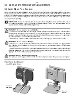
Page 44: ... 5 0 SEATING SYSTEM COMFORT ADJUSTMENTS SEATING SYSTEM COMFORT ADJUSTMENTS 5 7 1 Independent Calf Pad Adjustment cont d Malleable Calf Pad Adjustment Bendable Inner Steel Skeleton Fixed Mounting Position Malleable Calf Panel 5 7 2 Malleable Calf Panel for LNX Legrest Only The malleable calf panel provides a greater level of support without the need for a multitude of adjustments This unique one pi...

Page 45: ...ng bracket 2 3 Reinstall the lower mounting hardware through the chosen mounting hole and secure it in place Re tighten the upper mounting screw 96 90 101 116 112 106 86 76 79 Default Set Up 1 Right Hand Back Cane and Side Frame Shown Til t Ba ck Ca ne The tilt back cane angle can be manually adjusted to one of nine preset angles see image below There is a total available adjustment range of 40 fr...

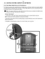
Page 46: ...he range of adjustment may be further increased if necessary by adjusting the height mounting position of the tilt back mount block on the back pan To Adjust Back Height 1 Loosen the 2 screws left right that secure the tilt back mount onto the tilt back canes 1 Note The back pan must be supported when loosening hardware 2 Slide the back pan back cushion vertically along the channel of tilt back mo...

Page 47: ...lateral height or remove Lift bracket up to release MAXX LATERAL TRUNK SUPPORT Loosen screws x2 to adjust bracket width Loosen screws x2 to adjust pad depth Swing lateral rearward Height Adjustment 1 Width Adjustment 2 Pad Depth Adjustment Angle Adjustment Swing AwayFeature left assembly shown 5 0 5 0 SEATING SYSTEM COMFORT ADJUSTMENTS SEATING SYSTEM COMFORT ADJUSTMENTS Loosen nuts screws x2 to ad...

Page 48: ...ion Concepts offers basic and adjustable headrest options for installation onto the wheelchair back cushion The headrest clamp hardware is designed to install into existing mounting holes in the back pan WARNING Injury hazard during use of the whelchair as a vehicle seat if a headrest is wrongly adjusted or not installed This can cause the neck to be hyperextended during collisions 48 Installation...

Page 49: ...ural belt is used to help the wheelchair user keep an optimum sitting position Correct use of the belt assists the user in sitting securely comfortably and well positioned in the wheelchair especially for users who experience difficulties with balance while sitting IMPORTANT The postural belt should be used whenever the wheelchair is occupied The belt should be tight enough to ensure that you are ...

Page 50: ...s of Postural Belts Your wheelchair can be fitted with the following postural belt types If your wheelchair has been fitted with a different belt to those listed below please ensure that you have received the manufacturer s documentation with regard to correct fitting and use 2 Point Padded Lap Belt Center pull push button padded lap belt Two points of attachment to the wheelchair Suitable for sup...

Page 51: ...ser 10 Check all of the wheelchair drive functions 11 Check that the rod ends on the tilt and recline actuators have been properly pinned if applic 12 Check the anti tipper latching system if applicable 13 Check that the anti tipper extensions are installed if required 14 If the front or rear anti tippers are adjustable check that they have been set to the appropriate postition for the user 15 Tes...

Page 52: ...operating conditions such as daily travel on steep slopes or in the case of use in medical care cases with frequently changing wheelchair users it is recommended to carry out intermediate checks on the brakes accessories and running gear The wheelchair operator is responsible for ensuring that the power wheelchair and seating system iremains in an operationally reliable condition Inadequate or neg...

Page 53: ...dware and Components inspect mounting hardware seating system to power base X X inspect all adjustment hardware to ensure nuts and screws are secure i e side rails recline module legrests foot plates receivers X X inspect for loose parts rattling sounds ensure all nuts and screws are secure X X Inspect that all pivot points are operating smoothly freely and secured do not overtighten X X Inspect A...

Page 54: ...he use of heavy grease or high viscosity lubricants as this can cause a build up of dirt and contaminates which could reduce overall performance 7 0 GENERAL MAINTENANCE SAFETY 7 0 GENERAL MAINTENANCE SAFETY Pivot Point Lubrication Tilt Elevate the seating system Use a clean rag to wipe away any dirt residue around pivots and along slide channels Lubricate main pivot points of the positioning modul...

Page 55: ...e life cycle of these electronics Smaller on board chargers are not sufficient to recharge rehab style power products Batteries that require more frequent charging or take longer to charge than normal may need to be replaced IMPORTANT INFORMATION ON BATTERY CHARGING NORMAL CHARGING Allow 8 hours for normal charging Note Note To prolong the life of a battery frequent charging is recommended rather ...

Page 56: ...to the illustration below for testing instructions WARNING Never attempt a voltage measurement with a test lead in the AMP A or MILLIAMP mA input terminal You may be injured or cause damage to the voltmeter 7 5 Battery Testing cont d 7 0 GENERAL MAINTENANCE SAFETY 7 0 GENERAL MAINTENANCE SAFETY ...

Page 57: ...ubleshooting information regarding the wheelchair powerbase electronics please refer to the Troubleshooting section of the Powerbase Owner s Manual provided separately NOTE For further assistance on these or any other issues please contact our Technical Service Department USA 888 433 6818 CAN 800 680 4191 ...

Page 58: ...he antenna mounted directly on the transmitting unit examples include cellular telephones citizen band CB radios walkie talkies security fire and police transceivers and other personal communication devices NOTE Some cellular telephones and similar devices transmit signals while they are ON even when they are not being used 2 Medium range mobile transceivers such as those used in police cars fire ...

Page 59: ...of nearby transmitters such as radio or TV stations and try to avoid coming close to them If unintended movement occurs turn the wheelchair off as soon as it is safe to do so Be aware that adding accessories or components or modifying the power positioning system may make it more susceptible to EMI Note There is no easy way to evaluate their effect on the overall immunity of the powered wheelchair...

Page 60: ...ll free 866 748 7943 Concord Ontario Fax 905 695 0138 L4K 3C1 Tech Service 800 680 4191 info motionconcepts com www www motionconcepts com USA Motion Concepts 700 Ensminger Rd Suite 112 Tel 716 447 0050 Tonawanda New York Tel toll free 866 433 6818 14150 Fax 888 433 6834 Tech Service 888 433 6818 ...

Reviews: