headline bars
tabs
continuation tabs
notes
warnings
headline bars
tabs
con
tinua
tion tabs
not
es
w
ar
nings
headline bars
tabs
continuation tabs
notes
warnings
model no. 009-0078-8 | contact us 1-888-942-6686
6
ASSEMBLY
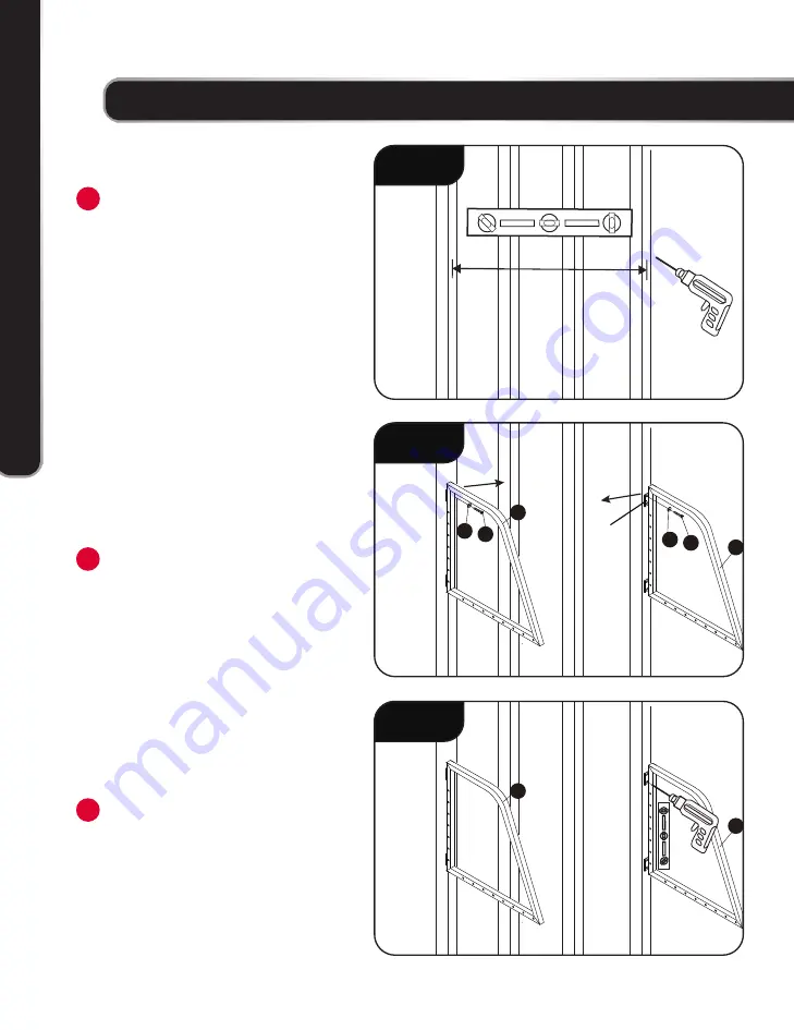
Plan for the proper location of the tire
rack. The product must be attached to a
wall surface with vertical studs, and the
supports will be positioned 48” (121.9
cm) (centre to centre) apart. Use a stud
finder (not included) to assist in locating
studs. Use a pencil to mark the top
mounting hole centres. Make sure holes
are level. Pre-drill the marked holes
using a 3/16” (4.8 mm) drill bit.
Note:
the tire rack must be mounted
directly into the wall studs; do not use
wall anchors to mount to sheetrock.
Note:
make sure the pilot holes that
pre-drilled are long enough, at least
longer than the lag screws provided.
Slide Washer (6) onto the Lag Screw
(5); insert Lag Screw (5) through the top
mounting hole of each Frame to hold
in place using a 13mm wrench (not
included). Do not tighten Lag Screw (5)
completely at this time.
Note:
Identify Left Frame or Right Frame
using the marking sticker on each,
make sure the Mounting Plates are to
the inside.
Note:
Don’t use an impact driver.
Make sure Left Frame (1) and Right
Frame (2) are vertically level using a
level. Use the remaining 3 mounting
holes in each as template, and drill the
holes on the wall studs.
1
3
2
ASSEMBL
Y
x
STEP 1
x
48” (centre to centre)
STEP 2
1
6 5
2
6 5
Mounting
Plate
STEP 3
1
2


