© Motor City Wash Works, Inc. 48285 Frank, Wixom Michigan 48393 U.S.A.
Phone: 248.313.0272 ▪ Fax: 248. 313.0271
8MANULHYDDOC0004 REV 1.0
www.motorcitywashworks.com
5
Start up new power pack instructions:
Start up new power pack instructions:
1. Fill tank with ISO 32 Hydraulic oil [Fill to top of sight gauge] *[1]
2. Disconnect the fittings on the lines for the hydraulic motor, hydraulic lines connected together to bypass
hydraulic motor on ALL equipment connected to this power pack to purge new lines.
3. Remove the orange cover to access the motor/pump coupling. [This can be put back on once proper electric
motor rotation has been confirmed]
4. Pump priming filler cap--remove and fill with Hydraulic oil you have used in tank to prime pump--when full
replace cap
5. Next step is to "BUMP ON" electric motor for no more than 5 seconds to check for correct rotation. [You can look
at coupling or fan on end of electric motor] When you have the correct rotation "arrow on motor is the rotation
direction you want to see the cooling fan move on the electric motor." DO NOT run motor in wrong direction for more
than 15 seconds as this will damage the pump seals.
6. With the proper pump rotation you can now run the pump to push fluid thru lines to remove them of debris for 5
minutes. This will allow the lines to be filled and cleaned to the return filter.
6A. Turn off and reconnect hydraulic motor hydraulic lines then verify proper rotation of Hydraulic motors. If
any are running backwards you need to swap the feed and return line at the hydraulic motor OR at the power pack,
whichever is easiest for you. [If you have only one side running in the wrong direction you will have to swap at the
motor that is spinning wrong.]
7. Calculate the RMP of the brush [count rotations for 15 seconds then multiply by 4]
8.Speed adjustment knob: Loosen jam nut to turn knob. clockwise [slower speed] counterclockwise [faster speed]
9. When done adjusting tighten jam nut to lock knob into place.
10. Save female JIC caps provided from feed and return ports. They are useful for future use.
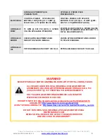
*[1] If using Water Glycol Hydraulic fluid clean inside of tank
CLEAN
before running pump.
[ONLY SEALED GEAR-MOTOR ASSEMBLIES CAN RUN WITH WATER/GLYCOL BASED FLUID]
*DO NOT RUN OPEN SEAL (BEARING-LESS) GEAR-MOTOR USING
WATER BASED FLUID!
*DOING SO WILL REDUCE THE LIFE OF THE GEAR-REDUCER
AND WILL VOID YOUR WARRANTY!
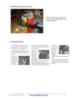
DESCRIPTION OF PARTS
1.
Low level switch:
[dry contact] it is N.O [normally open] or N.C. [normally closed] depending
on the float direction. It can be flipped for opposite operation. It will need to be removed
from tank and it has a cotter pin that needs to be removed to rotate the float bobber that
changes the signal from normally open or normally closed. [typical operation is normally
open] "not sending an input when tank full" [Program input on car wash controller side to
"CRITICAL FAULT" this will disable wash when loss of fluid has happened, protecting the
pump from failing from loss of oil.] Lastly the stem is adjustable and is best used in its highest
position so if there is a leak the float will change states sooner disabling the pump and will
save from losing a lot of fluid.


