background image

*NOTE: 50Hz will increase all delay timers by 20%

MOTORSAVER

®

 460-VBM SPECIFICATIONS

3-Phase Line Voltage

190–480VAC (nominal)

Frequency

50*/60Hz

Low Voltage (adjustable trip point)

     Trip

185–480VAC  (adjustable)

     Reset

Trip setting plus 3%

High Voltage (adjustable)

     Trip

208-528VAC  (adjustable)

     Reset

Trip setting minus 3%

Voltage Unbalance (NEMA)

     Trip

6%

     Reset

5%

Trip Delay Time


Low, High and Voltage Unbalance  

1–30 seconds (adjustable)


Single-Phasing Faults (>25% UB)  

1 second (fixed)

Restart Delay Time

After a fault or power loss

1–500 seconds (adjustable)

Output Contact Rating – DPST

     Pilot Duty

480VA @ 240VAC

     General Purpose

10A @ 240VAC

Power Consumption

6 Watts (max.)

Weight

14 oz.

Enclosure

Polycarbonate

Terminal

     Torque

6 in.-lbs. (max.)

     Wire AWG

12-20 AWG

Safety Marks

UL

UL508 (File #E68520)

CE

IEC 60947-6-2

Standards Passed

      Electrostatic Discharge (ESD)

IEC 1000-4-2, Level 3, 6kV contact, 8kV air

     Radio Frequency Immunity,
     Radiated

159 MHz, 10V/m

     Fast Transient Burst

IEC 1000-4-4, Level 3, 3.5kV input power and controls

Surge

     IEC

IEC 1000-4-5, Level 3, 4kV line-to-line;
Level 4, 4kV line-to-ground

     ANSI/IEEE

C62.41 Surge and Ring Wave Compliance to a level
of  6kV line-to-line

     Hi-Potential Test

Meets UL508
(2 x rated V +1000V for 1 minute)

Environmental

     Temperature Range

Ambient Operating: -40

°

 to 70

°

C (-40

°

 to 158

°

F)

Ambient Storage: -40° to 80°C (-40° to 176°F)

     Class of Protection

IP20, NEMA 1 (Finger Safe)

     Relative Humidity

10–95%, non-condensing per IEC 68-2-3

Phone: 800.894.0412 - Fax: 888.723.4773 - Web: www.clrwtr.com - Email: info@clrwtr.com

Summary of Contents for SymCom 460-VBM

Page 1: ...in a convenient location in or near the motor control panel If the location is wet or dusty the MotorSaver should be mounted in a NEMA 4 or 12 enclosure The MotorSaver can be mounted to a back panel...

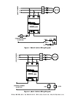
Page 2: ...460 Figure 1 Motor Control Wiring Diagram LIGHT 460 Figure 2 Alarm Control Wiring Diagram Phone 800 894 0412 Fax 888 723 4773 Web www clrwtr com Email info clrwtr com...

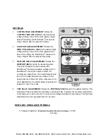
Page 3: ...ceptable voltage and the MotorSaver closing its output contacts For compressor applications the restart delay should be set for the approximate time it takes for the head pressure to bleed off of the...

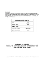
Page 4: ...light will illuminate If the contacts do not energize and the RUN light does not illuminate see the TROUBLESHOOTING section CONGRATULATIONS YOU HAVE JUST INSTALLED THE FINEST MOTOR PROTECTION AVAILAB...

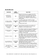
Page 5: ...tages and calculate the unbalance according to the formula on page 3 If the voltage unbalance does not exceed 5 call SymCom at 800 843 8848 or 605 348 5580 Red light is on steady RED The voltage is ou...

Page 6: ...ht 14 oz Enclosure Polycarbonate Terminal Torque 6 in lbs max Wire AWG 12 20 AWG Safety Marks UL UL508 File E68520 CE IEC 60947 6 2 Standards Passed Electrostatic Discharge ESD IEC 1000 4 2 Level 3 6k...

Page 7: ...l other products manufactured by SymCom shall be warranted against defects in material or workmanship for a period of two 2 years from the date of manufacture For complete information on warranty liab...

Reviews: