12A
12B
EN
EN
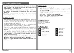
All tests must be performed by qualified personnel due to serious danger associated
with the misuse of electrical systems!
AUTOMATISM
8μF (230V) / 20μF (110V)
Capacitor
1
2
3
2
COM 1
COM 2
COM
Ground Wire
Phase 2
Phase 1
Open
Close
Motor
Power Supply 1
Power Supply 2
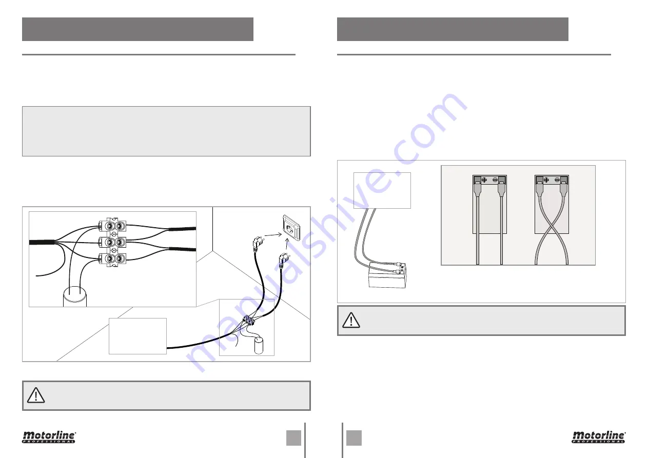
To detect if the malfunction is on the control board or on the motor is, sometimes, necessary
to perform tests with connection directly to a 110V/230V power supply.
For this, it is necessary to interpose a capacitor on the connection in order to the automatism
to work (check the type of capacitor to be used in the product manual). The diagram below,
shows how to make that connection and how to merge the different components wires.
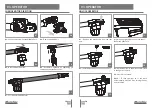
01
•
Connect the power wires to the terminal, as shown below.
02
•
Connect the automatism wires in the terminal, interposing a capacitor in the opening
and closing wires.
03
•
Once these connections are completed, connect to a 110V/230V power outlet, depending
on the motor/control board in test.
NOTES:
•
To perform the tests, there is no need to remove the automatism from the place it is installed,
because in this way, it is possible to understand if the automatism can function properly
connected directly to the current.
•
You should use a new capacitor during this test to ensure that the problem does not lie on it.
All tests must be performed by qualified personnel due to serious danger associated
with the misuse of electrical systems!
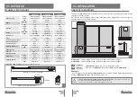
To detect which are the components with problems in a 24V LINCE automatism instalation,
it's sometimes necessary to run a test directly to a external power supply (another 24V
battery).
The diagram below shows how to connect the motor to the battery.
NOTES:
• To make these tests it isn't necessary to remove it from the location where it is installed,
because in this way, you can understand of the automatism works properly directly
connected to the external battery.
• Once you connect the wires to a battery 24V, the motor must work for one direction. To test
the opposite movement, change the position of the wires connected to the battery.
06. COMPONENTS TEST
06. COMPONENTS TEST
230V/110V MOTOR
24V MOTOR
AUTOMATISM
24V Battery
24V Battery
Motor rotates
to one direction
(eg: right)
Motor rotates in the
opposite direction
(eg: left)
24V Battery
Motor's wires


