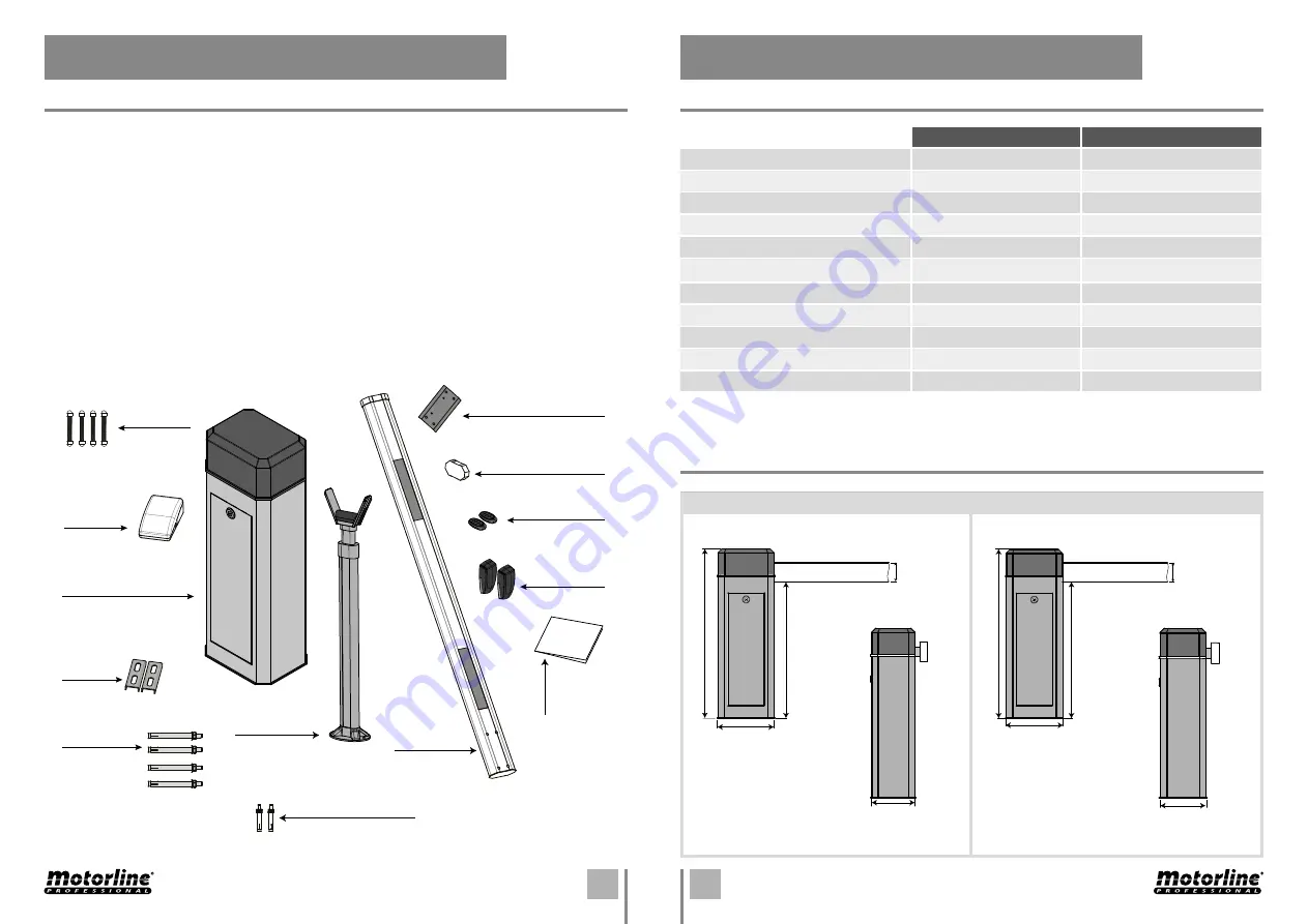
background image

3A

3B

855mm

1050mm

100mm

360mm 

275mm 

MBM8  

MBM11 

 850mm

1140mm

140mm

460mm 

330mm 

EN

EN

02. PACKAGE

03. AUTOMATISM

INSIDE PACKAGE

TECHNICAL SPECIFICATIONS

DIMENSIONS

01 • electromechanical barrier

01 • control board

02 • transmitter

01 • aluminium boom

01 • boom support

01 • external photocells set

02 • fastening metal plates

01 • boom fastening metal plate

04 • M16 bolts with bushings

04 • boom fastening screws 

02 • boom support fastening screws

01 • boom cover 

01 • installer and user’s manual 

Inside the package you will find the following components:

MBM8

MBM11

• Barrier’s Power Supply

AC 230V 50/60Hz

AC 230V 50/60Hz

• Motor’s Voltage

AC 230V

AC 230V

• Power


180W

300W

• Current

1A

2A

• RPM 

2800 RPM

480 RPM

• Noise level

<60 db

<70 db

• Working temperature

-25°C to 65°C

-25°C to 65°C

• Thermal protection

120°C

140°C

• Protection level 

IP55

IP55

• Working frequency

Intense

Intense

• Opening/Closing time

6 seg

11 seg

Photocells

Transmitter

Boom cover

Boom fastening

metal plate

Boom 

fastening 

screws

Control 

board

Electromechanical 

barrier 

Fastening

metal

plates

M16 bolts with 

bushings

Boom support

fastening screws

Boom 

support

User’s

manual

Alluminium 

boom

Summary of Contents for MBM11

Page 1: ...V3 1 REV 10 2019 MBM8 MBM11 EN INSTALLER AND USER S MANUAL...

Page 2: ...LOSING INSTALLATION SITE PREPARATION DIMENSIONS BARRIER S FIXATION BOOM ASSEMBLY 01 SAFETY INSTRUCTIONS 02 PACKAGE 03 THE AUTOMATISM 04 INSTALATION 00 CONTENT INDEX BOOM SUPPORT INSTALLATION TOP COVER...

Page 3: ...ls etc are susceptible to electric shock by direct or indirect contact with electricity Be cautious when handling the product and observe all safety procedures in this manual It is important for your...

Page 4: ...er s manual Inside the package you will find the following components MBM8 MBM11 Barrier s Power Supply AC 230V 50 60Hz AC 230V 50 60Hz Motor s Voltage AC 230V AC 230V Power 180W 300W Current 1A 2A RP...

Page 5: ...tion of the barrier right or left will open or close the boom 20mm height of foundation above soil 20mm height of foundation above soil 500 mm total height of foundation 500 mm total height of foundat...

Page 6: ...metal plates and fix the barrier to the ground tightening the nuts supplied with the product To assemble the boom you must place the boom on the barrier fixing plate and align the four holes on each p...

Page 7: ...de 3 The hooks that secure the top cover are also rotated and release the cover Before starting the tuning of the springs is necessary to remove the screw identified in the illustration ADJUSTMENT To...

Page 8: ...ts you just need to loosen the bolts that fix them rotate them and fasten the bolts to fix them on that position For the correct operation of the barrier please pay attention to the information in the...

Page 9: ...nnected directly to the power supply works properly The order to connect the capacitor s cables on the barrier s cables is not important You just have to connect one on the Brown cable and the other o...

Reviews: