


4A
4B
130 a 175mm
130 a 160mm
150 a 290mm
150 a 200mm
350mm
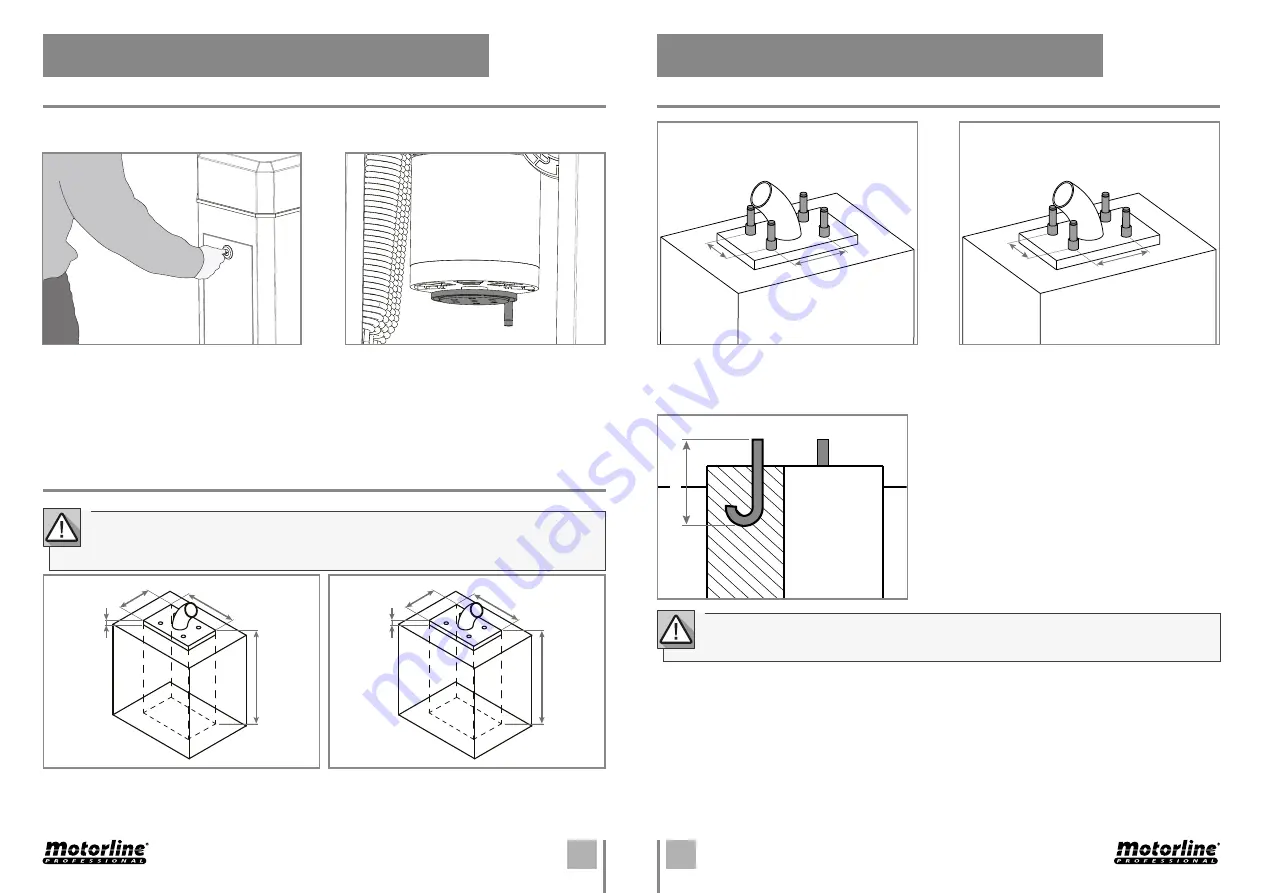
MBM8
MBM11
MBM8
MBM11
EN
EN
04. INSTALLATION
OPENING/CLOSING
INSTALLATION SITE PREPARATION
04. INSTALLATION
1 • Open the door using the key supplied with the
barrier. Rotate the key to unlock the door and
pull it towards outside.
On the interior, you will have access to the
unlocking system.
1 • Create a foundation in cement on the soil. The dimensions on the side image are the minimum to
maintain, so they can be superiors but never inferiors.
You must leave one or more tubes for the cables of the different components to pass through the
foundation to the barrier (photocells, wall starts, key selectors, etc).
2 • The unlocking is made by rotating the disc at
the bottom of the motor, highlighted/shaded on
the image on the side.
To open or close you must try to rotate the disk
clockwise or counter-clockwise, that depending
on the orientation of the barrier (right or left) will
open or close the boom.
20mm
(height of
foundation
above soil)
20mm
(height of
foundation
above soil)
500 mm
(total
height of
foundation)
500 mm
(total
height of
foundation)
350 mm
400 mm
450 mm
550 mm
In case of power failure, the barrier is equipped with a manual unlocking and locking system. Follow the
instructions bellow to unlock or lock the barrier.
INSTALLATION SITE PREPARATION
It’s important that this order of installation is respected!
Otherwise we can’t assure the correct installation of the barrier and it may not work properly.
To note that each barrier has its own measures to create the holes for the bolts!
ALTERNATIVE • During installation, you can replace the
bolts supplied by metal hooks, soldering them on the
cement foundation while it is still fresh.
You must pay attention to the above image’s dimensions
when placing the hooks.
2 •
Solder the bolts with bushings on the foundation while the cement is still fresh.
It is also necessary to respect the dimensions on the side image when soldering the bolts, so that the
barrier can be installed.


