


8A
8B
EN
EN
05. COMPONENT TEST
CONNECTIONS SCHEME
MAINTENANCE
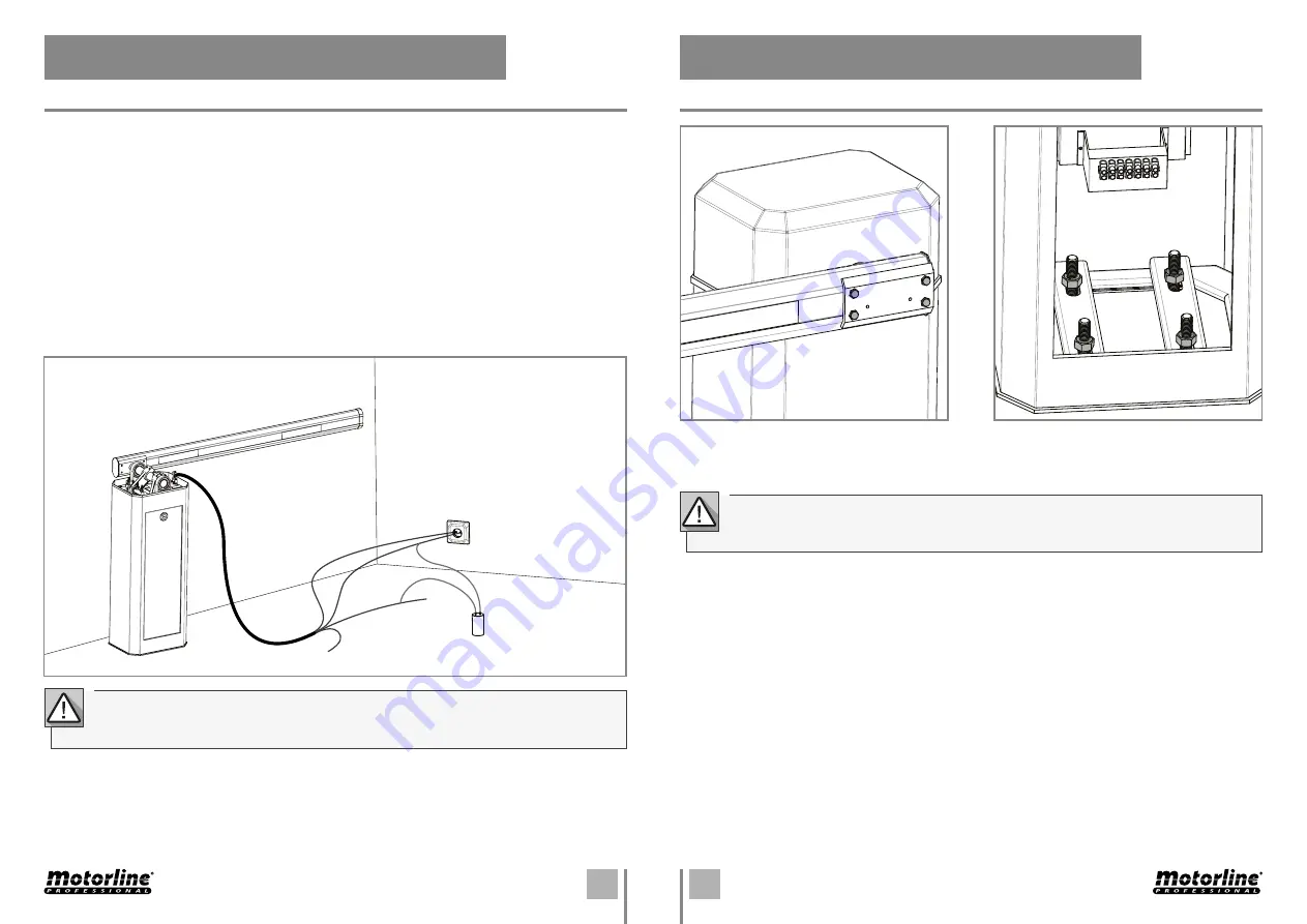
06. MAINTENANCE
BARRIER
Common (Blue)
Black
Brown
Capacitor 22 µF
Power supply 230V
ground wire
To detect which are the components with problems in barrier’s installation, sometimes it will be needed to
run some tests with direct connection to a 230V power supply. For that, it’s necessary to interpolate a 22µF
capacitor in between the connection for the barrier to operate.
At the bellow scheme, it’s shown how the connection must be done interpolating the different device’s
cables.
NOTES:
• To run the test you don’t need to remove the barrier from the installation site where it is installed. This
way you can more easily find out if the barrier, connected directly to the power supply, works properly.
• The order to connect the capacitor’s cables on the barrier’s cables is not important. You just have to
connect one on the Brown cable and the other on the Black cable.
• The common cable of the barrier must always be connected to the power supply.
• To invert the operating direction, you just need to change the Black cable with the Brown cable of the
barrier, on the connection to the power supply.
Check tightness of the screws that fix the boom
to the barrier’s body.
Check if the fastening metal plates didn’t suffer
any modification with the consistent utilization
to assure the proper functioning of the barrier.
IMPORTANT: All tests must be made by qualified technicians due to the serious danger
related to the incorrect use of electronic systems!
These maintenance procedures must be realized every year to assure the well functioning
of the automatism.


