18A
18B
EN
EN
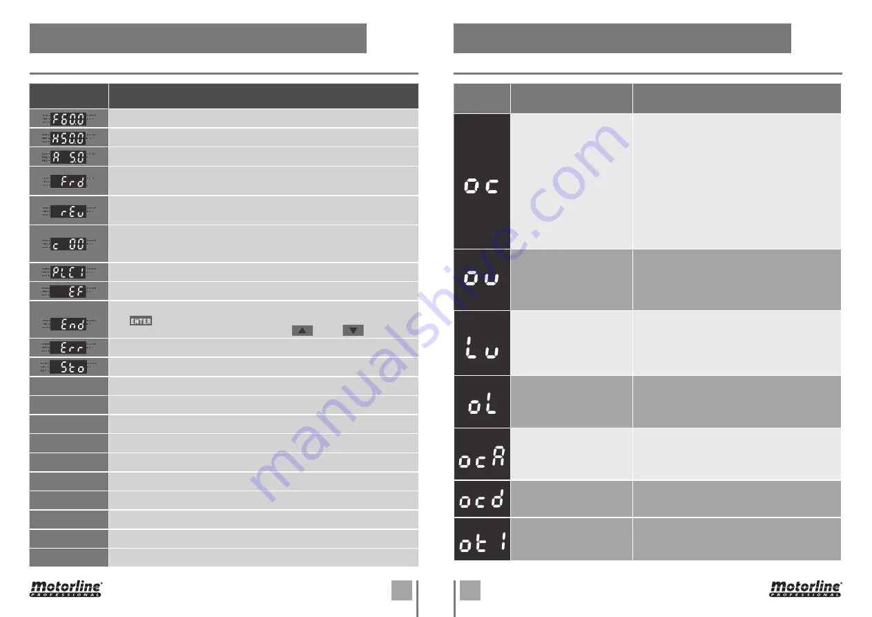
Fault identifi-
cation
Description of failure
Corrections
OVERCURRENT
Abnormal increase of current.
01 •
Check if the motor power corresponds to the output
power of the AC motor inverter.
02 •
Check for possible short circuits on U / T1, V / T2, W
/ T3 wiring connections.
03 •
Check for possible short circuits in the wire
connections between the AC motor inverter and the
motor and ground wire.
04 •
Check for loose contacts between the AC motor
inverter and the motor.
05 •
Check for possible overload conditions on the motor.
06 •
After a short circuit, if there are still anomalies in
the operation of the AC motor inverter, you must send
the product to the manufacturer.
OVERVOLTAGE
The DC voltage has exceeded
the maximum allowed value.
01 •
Check if the input voltage of the AC motor inverter is
within the rated voltage class.
02 •
Check for possible voltage variations.
03 •
Check if the power required for the brake is within the
specified limits.
LOW VOLTAGE
The AC motor inverter detects
that the DC terminal voltage is
below the minimum value.
01 •
Check if the input voltage of the AC motor inverter is
within the rated voltage class.
02 •
Check for abnormal motor load.
03 •
Check if the input power connections are correct with
R-S-T (for 3-phase models) without losing the phase.
OVERLOAD
The AC inverter detects
excessive current at the control
output.
01 •
Check if the motor is overloaded.
02 •
Use the following model with AC motor inverter
power.
OVERLOAD DURING
ACCELERATION
01 •
Short-circuit at the motor output: Check that the
isolation on the output lines is in good condition.
02 •
Acceleration time too short: Increase the acceleration
time.
OVERCURRENT DURING
DECELERATION
01 •
Short-circuit at the motor output: Check that the
isolation on the output lines is in good condition.
DETECTION OF EFFORT AND
EXCESS OF CONSUMPTION
01 •
Check parameter 06.04 and set lower sensitivity (set
a value closer to 200%).
02 •
Check if the door is stucked at some point.
08. TROUBLESHOOTING
INSTRUCTIONS FOR CONSUMERS AND SPECIALIZED TECHNICIANS
07. PROGRAMMING
Message
displayed
Description
Displays the master frequency of the AC inverter.
Displays the effective output frequency at the U / T1, V / T2, and W / T3 terminals.
Displays the output current at the U / T1, V / T2, and W / T3 terminals.
Door in opening - Displays the opening operation status on the AC inverter.
Door in closing - Displays the closing operation status on the AC inverter.
Input indications.
This indication is displayed whenever there is no common input or the PLC1
parameter is in PLC0. It may also happen a short circuit in the 24V.
Mandatory mode for operation (
do not change this menu
)
External fault
Displays "End" for approximately 1 second if the input is accepted by pressing
the button. After a value is set in the parameter, the new value is
automatically added to the memory. To modify an entry, use the and buttons.
Displays “Err” if the input is invalid.
STOP enable the crank sensor
C111
Limit switch enabled and opening button pressed.
C222
Limit switch enabled and closing button pressed.
C333
Nothing activated.
C444
Opening limit switch enabled and descent button pressed
C555
Closing limit switch enabled and descent button pressed
C888
Photocells enabled.
C101
Ascent limit switch enabled.
C202
Descent limit switch enabled.
C999
Emergency stop, STOP or crank sensor.
C800
No connection/limit switches and safety.
LED DISPLAY MESSAGES


