
10A
10B
9A
9B
EN
EN
06
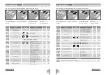
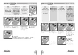
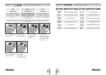
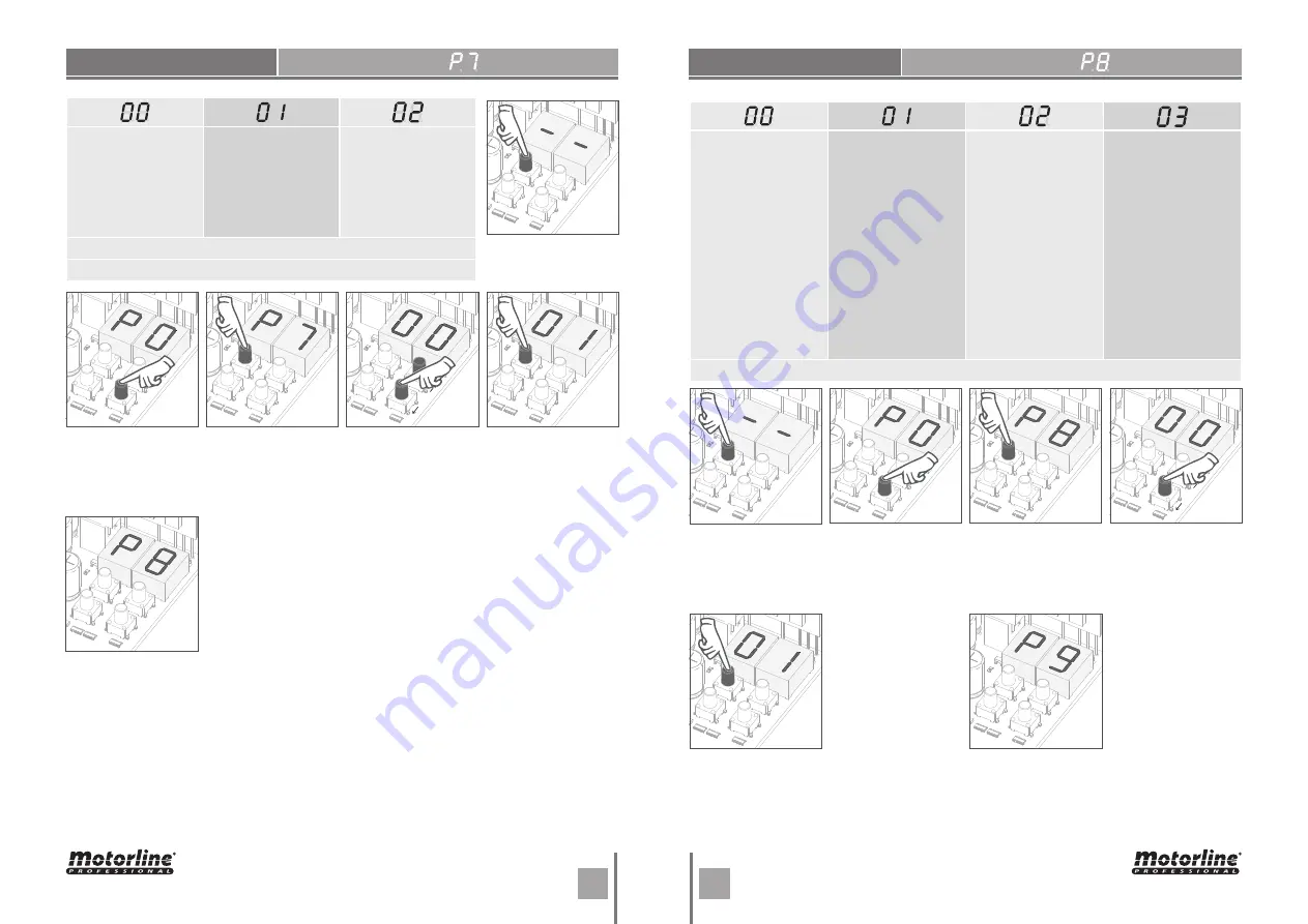
• P8 appears.
To program P8, continue in step 3 from P8 menu (page 9B).
To exit the programming press ↑↓ simultaneously.
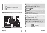
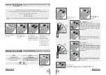
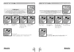
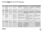
Functioning in automatic
mode
1st
impulse -
OPENS
2nd
impulse -
STOPS,
TIMER AND CLOSES
(IF P4>00)
3rd
impulse -
INVERTS
Functioning in step by
step mode
1st
impulse -
OPENS
2nd
impulse -
STOPS
3rd
impulse -
CLOSES
4th
impulse -
STOPS
If is fully open and timed,
the barrier closes
Functioning in
condominium
mode
Does not accept orders
during opening and
pause time, in closure it
reverses (either by trans-
mitter or control board
start button)
factory default (
02
)
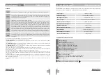
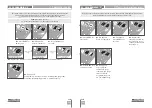
This menu allows you to set the barrier's operating mode.
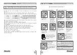
02
• P0 appears.
Press ↓ seven times.
01
• Press MENU for 3
seconds.
03
• P7 appears.
Press MENU for 3
seconds.
05
• Press MENU to
save the defined
function.
04
• Appears the
function currently set.
If you want, change
the function to 00, 01
or 02, using
↑↓.
OPERATING LOGIC
04. PROGRAMMING "P"
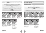
06
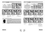
• P9 appears.
To program P9,
continue in step 3
from P9 menu (page
10A). To exit the
programming press
↑↓ simultaneously.
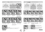
FLASHING LIGHT
04
• Appears the
function currently set.
If you want, change
the function to 00, 01
or 02, using
↑↓.
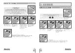
Intermittent
(opening and closing)
During the barrier's
opening/closing
movement, the
flashing light will work
intermittently.
During movement
of
the barrier (opening
and closing), the
flashing light will
remain lit.
Courtesy light
The light will remain
lit during the time
defined in the E2
menu (page 12B).
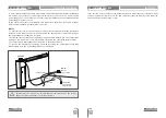
Electromagnet
With the barrier
closed, the control
board continuously
feeds the magnetic
lock for a second
before it initiates any
opening maneuvers.
The output is fed again
for a second before it
fully closes, so as soon
as the maneuver is
completed, the boom
is attached with the
electric lock.
Factory defaut (
00
)
01
• Press MENU for 3
seconds.
02
• P0 appears.
Press ↓ eight times.
03
• P8 appears.
Press MENU for 3
seconds.
05
• Press MENU to
save the defined
function.
04. PROGRAMMING "P"


