
15A
15B
14A
14B
EN
EN
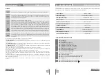
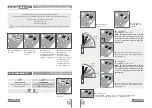
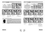
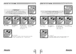
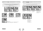
Continuous light
Flashing light
Pre-Flashlight
The control board activates
the output during the opening,
pause and close in continuous
mode.
The control board activates
the output during the opening,
pause and close in flashing
mode.
The control board activates
the flashing light output for 3
seconds before starting any
opening or closing maneuver.
(factory default
01
)
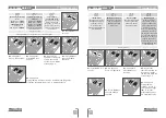
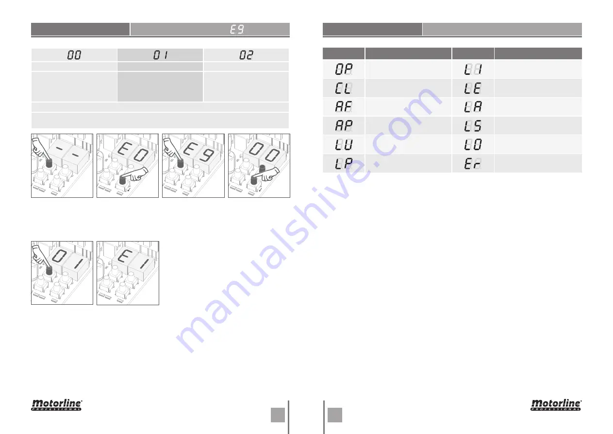
This menu allows you to select the functioning mode of the four signs, fixed or intermittent
output. page 10A)
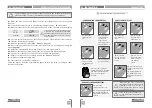
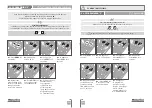
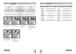
03
• E9 appears.
Press MENU for 3
seconds.
01
• Press MENU for
10 seconds.
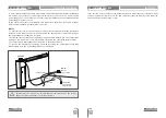
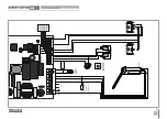
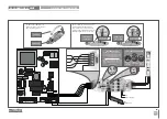
RGB OUTPUT
05
• Press MENU for 3
seconds to save the
defined function.
06
• E1 appears.
To exit the
programming press
↑↓ simultaneously.
02
• E0 appears.
Press ↓ nine times.
05. PROGRAMMING "E"
04
• Appears the
function currently set.
If you want, change
the function to 00 or
01, using
↑↓.
MENU
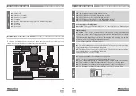
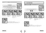
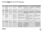
DESCRIPTION
MENU
DESCRIPTION
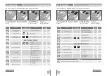
Opening limit-switch enabled
Inversion by effort
Closing limit-switch enabled
obstructed photocells
In pause time
Security Band under pressure
In pedestrian pause time
Pedestrian button being
pressed
Memory full
Start button being pressed
Memory full (pedestrian)
Sensibility detection failure
DISPLAY INDICATIONS
06. DISPLAY


