background image

19

12V

RG

R

B

G

OV

+

-

V+

G

R
B

RG

0V

LS LO FO FC

LA LE

FO

LO

LS

FC

1 2 3 4 5

EN

LE

LA

+V

1 2 3 4 5

R

Y

24V

G

B

1 2 3 4 5

24V

1 2

1

2

F

FE

N

P

N

AB COM

1 2 3 4 5 6 7 8 9

18

EN

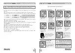
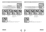
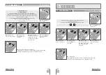
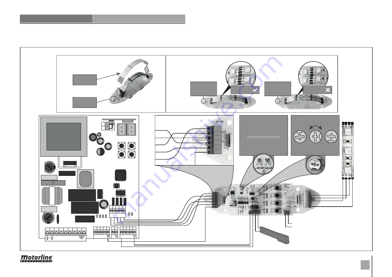
To remove the LED strip it is 

only necessary to remove the 

two connecting points.

8k2 

safety band

12V 

Power Supply

LED Strip

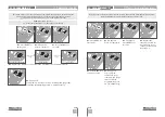
The positioning is based on the 

existing letters of the LED strip. 

It is considered as incorrect posi-

tion when the letters are inverted 

(with the light sensor on the left).
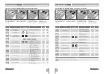
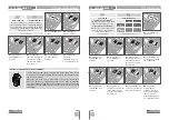
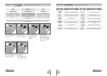
L.SENSE - 

Only lights up when it 

detects that the brightness level 

is above the value regulated on 

the potentiometer.  

INFORMATIVE LEDS

LIGHT SENSOR ADJUSTMENT

S.EDGE - 

Only lights up when you 

have a 8k2 safety band connected. 

It turns off when the band is acti-

vated/pressed.

More sen-

sitive to 

the light

Less sen-

sitive to 

the light

Interme-

diate level

LED strip

Light sensor 

on the left

Light sensor 

on the left

Correct position:

READABLE LETTERS

Incorrect position:

INVERTED LETTERS

Light sensor

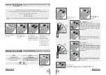
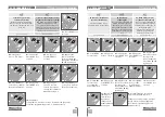
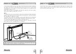
FLASHING LIGHT CONNECTION

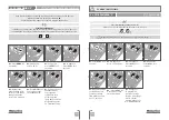
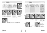
09. CONNECTION SCHEME

Summary of Contents for MC50BR

Page 1: ...24V 1 2 v 164 br EN USER INSTALLER MANUAL MC50BR...

Page 2: ...CELERATION SPEED P9 DISTANCE PROGRAMMING P1 SETTING THE DECELERATION TIME E3 FOLLOW ME P7 OPERATING LOGIC P4 PAUSE TIME E7 MANEUVERS COUNTER E0 PRESENT MAN P2 SETTING STRENGTH AND SENSITIVITY P8 FLASH...

Page 3: ...to the automation components and or their accessories Keep remote controls away from children to prevent the automated system from being activated involuntarily The customer shall not under any circu...

Page 4: ...riggering is visible on the display OP opening limit switch activated and CL opening limit switch activated It is mandatory the use of limit switches CN4 Safety circuits 01 This input allows connectio...

Page 5: ...the display does not match the barrier s movement turn off the control board from the power supply e swap the 5 and 7 wires from CN1 and check if it is correct with 3 and 4 from CN2 ESSENTIAL STEPS F...

Page 6: ...rity Band Disabled Security Band Activated 8k2 input NC input Band in closure Band in opening 00 01 00 8B OperatiNG logic Automatic mode function Step by step mode function Mode condominium function 0...

Page 7: ...mming press simultaneously 01 Press MENU for 3 seconds min max 0s COURSE AUTOMATIC PROGRAMMING 04 PROGRAMMING P RAMP ADJUSTMENT 04 PROGRAMMING P 9s 02 P0 appears Press once 03 P1 appears Press MENU fo...

Page 8: ...and reverse the direction Factory default 00 min max 1 9 07 P3 appears not available menu To program P4 continue in step 3 from P4 menu page 7B To exit the programming press simultaneously 04 PROGRAM...

Page 9: ...you want change the it between 00 and 01 using 08 Appears the function set from factory If you want change the it between 00 and 01 using 11 Appears the function set from factory If you want change t...

Page 10: ...on to 00 01 or 02 using OPERATING LOGIC 04 PROGRAMMING P 06 P9 appears To program P9 continue in step 3 from P9 menu page 10A To exit the programming press simultaneously FLASHING LIGHT 04 Appears the...

Page 11: ...itter 03 P9 appears Press MENU for 3 seconds 05 Press MENU to save the defined function 01 Press MENU for 3 seconds 02 P0 appears Press 9 times 04 Appears the function currently set If you want change...

Page 12: ...fined function 04 Appears the function currently set If you want change the function to 00 or 01 using SOFT START 05 PROGRAMMING E COURTESY LIGHT TIME 01 Press MENU for 10 seconds 02 E0 appears Press...

Page 13: ...Follow me function P5 have to be set with HE 01 HC 00 see page 9A Factory default 01 05 PROGRAMMING E 04 Appears the function currently set If you want change the function to 00 or 01 using min max 4...

Page 14: ...06 E8 appears To program E8 continue in step 3 from E8 menu page 13B To exit the programming press simultaneously 05 PROGRAMMING E 3 dozens 1 hundreds of thousands 2 thousands RESET RESTORE FACTORY V...

Page 15: ...10A 03 E9 appears Press MENU for 3 seconds 01 Press MENU for 10 seconds RGB OUTPUT 05 Press MENU for 3 seconds to save the defined function 06 E1 appears To exit the programming press simultaneously 0...

Page 16: ...etween the capacitator and the automatism wires is not important as long as it is connected one with the brown wire and the other with the black wire The common wire must always be connected to the po...

Page 17: ...ge 15A 3 If the motor works the problem is from control board Pull it out and send it to our MOTORLINE technical services for diagnosis 4 If the motor doesn t work remove them from installation site a...

Page 18: ...5 24V 1 2 F FE N P N AB COM 1 2 3 4 5 6 7 8 9 DV 12 24V DV 12 24V COM NC 230v 17 EN CONNECTIONS MAP 09 CONNECTION SCHEME Flashing Light Barrier See diagram on page 19 Photocell Photocell CAPACITOR 10...

Page 19: ...when the letters are inverted with the light sensor on the left L SENSE Only lights up when it detects that the brightness level is above the value regulated on the potentiometer INFORMATIVE LEDS LIGH...

Reviews: