
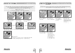
6A
6B
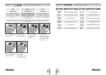
5A
5B
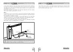
EN
EN
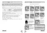
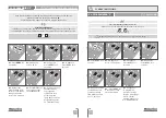
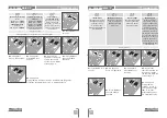
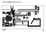
• Use ↑↓ to navigate
through the menus.
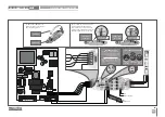
• Use ↑↓ to navigate
through the menus.
• To access the P menu
press the MENU key
for 3sec.
• To access the E menu
press the MENU key
for 10sec.
• We can only go into programming with a electrically closed barrier.
• We can only go into programming with a electrically closed barrier.
• Press MENU when
you want to confirm
access to a menu.
• Press MENU when
you want to confirm
access to a menu.
• Press ↑↓
simultaneously to
exit programming.
• Press ↑↓
simultaneously to
exit programming.
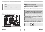
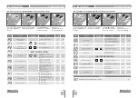
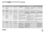
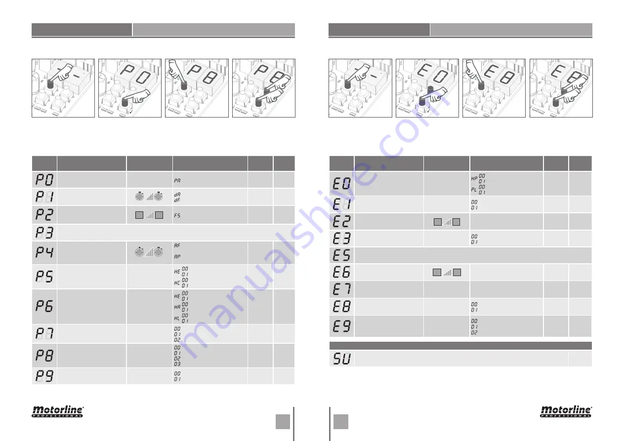
MENU
FUNCTION
MAX. MIN.
PROGRAMMABLE
STATE
FACTORY
VALUE
PAGE
Course automatic
programming
-
Automatic Programming
-
6A
Ramp adjustment
Opening ramp
Closing ramp
03
03
6B
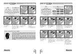
Force and
sensibility adjustment
Sensibility adjustment
00
7A
INACCESSIBLE MENU
Pause time
Total closure pause time
adjustment
Pedestrian closure pause time
adjustment
3
sec.
7B
Photocells programming
-
photocells Disabled
photocells Activated
Photocells in closing
Photocells in opening
00
00
8A
Safety band
-
Security Band Disabled
Security Band Activated
8k2 input
NC input
Band in closure
Band in opening
00
01
00
8B
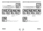
OperatiNG logic
-
Automatic mode function
Step by step mode function
Mode condominium function
02
9A
Flashing light
-
Flashing (opening and closing)
Step by step mode function
Courtesy light
Electromagnet
00
9B
Distance programming
-
Distance PGM OFF
Distance PGM ON
00
10A
min.
max.
0s
min.
max.
1
9
99s
min.
max.
1s
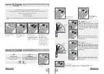
MENU
FUNCTION
MÁX. MIN.
PROGRAMABLE
STATE
FACTORY
VALUE
PAGE
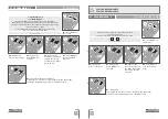
Present Man
-
Deactivates present man
Activates present man
Disables push buttons mode
Disables push buttons mode
00
00
10B
Soft start
-
Deactivates Soft start
Activates Soft start
00
11A
Courtesy light time
Courtesy light time adjustment
03
11B
Follow me
-
Deactivates follow me
Activates follow me
00
12A
INACCESSIBLE MENU
Deceleration speed
Deceleration speed adjustment
09
12B
Operation counter
-
Shows the number of maneuvers
-
13A
Reset - Restore factory settings
-
Deactivated
Reset activated
00
13B
RGB Output
-
Continued output
Intermittent output
Pre-Flashlight
01
14A
min.
max.
0
99
min.
max.
1
9
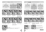
TRANSMITTER
Transmitter programming for total opening.
4B
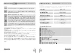
"E" MENU FUNCTIONS
03. INSTALLATION
"P" MENU FUNCTIONS
03. INSTALLATION
9s


