8
EN
04. DIP SWITCH
DIP SWITCH CONFIGURATION
To the control board be able to identify the task of each readers interconnected in an access control system, it is necessary that each of these devices has a unique ID.
This ID is crucial to identify the task that each
device performs and which port/access it is installed on
.
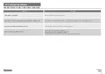
The definition is done through the dip switch board on the back of each reader, according to the following table:
• Connecting two or more devices with the same ID to a switch will create a communication conflict and none will work correctly.
ID
Dip switch
Door
Function
Without ID
ON
1 2 3 4 5 6
-
-
1
ON
1 2 3 4 5 6
Door 1
Entrance
2
ON
1 2 3 4 5 6
Exit
3
ON
1 2 3 4 5 6
Door 2
Entrance
4
ON
1 2 3 4 5 6
Exit
5
ON
1 2 3 4 5 6
Door 3
Entrance
6
ON
1 2 3 4 5 6
Exit
7
ON
1 2 3 4 5 6
Door 4
Entrance
8
ON
1 2 3 4 5 6
Exit
9
ON
1 2 3 4 5 6
Door 5
Entrance
ID
Dip switch
Door
Function
10
ON
1 2 3 4 5 6
Door 5
Exit
11
ON
1 2 3 4 5 6
Door 6
Entrance
12
ON
1 2 3 4 5 6
Exit
13
ON
1 2 3 4 5 6
Door 7
Entrance
14
ON
1 2 3 4 5 6
Exit
15
ON
1 2 3 4 5 6
Door 8
Entrance
16
ON
1 2 3 4 5 6
Exit
17
ON
1 2 3 4 5 6
Door 9
Entrance
18
ON
1 2 3 4 5 6
Exit
19
ON
1 2 3 4 5 6
Door 10
Entrance


