5A
5B
1
5
6
2
3
4
7
8
EN
EN
02. OPERATOR
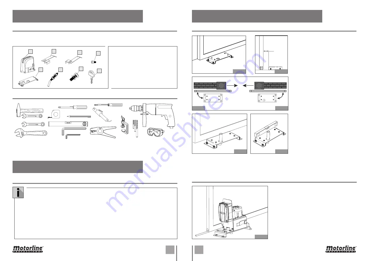
ACCESSORIES
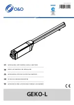
PREPARING THE FOUNDATION PLATE
PRELIMINARY CHECKS
03. INSTALLATION
03. INSTALLATION
You must check the operator packing before installing the automated system.
1 •
1 Motor
2 •
1 Left limit switch plate
3 •
1 Right limit switch plate
4 •
4 Screw DIN912 M5x10
5 •
1 Foundation plate
6 •
4 Ground Fixation screw
7 •
4 Motor Fixation screw
8 •
2 Key
INSTALLATION TOOLS
POSITIONING THE OPERATOR
Fit the 4 supplied nuts, as shown in Fig. 07
and Fig. 08, in the 4 holes of the plate.
1 •
The foundation plate must be located
as shown in Fig. 9a (right closing) or Fig. 9b
(left closing) to ensure the rack and pinion
match correctly.
2 •
Put the foundation plate to the floor,
using adequate expansion plugs and
provide one or more tubes for routing the
electric cables through the plate (Fig10
and 11).
Using a level, check if the plate is perfectly
horizontal.
Lay the electric cables to connect motor to accessories
and power supply as shown in page 4B.
To facilitate making the connections, allow the cables
to project by the required length for connection to the
control board, transformer and etc (if provided).
Position the operator on the plate, using the supplied
screws as shown in Fig. 12.
59mm
90º
90º
To ensure safety and an efficiently operating automated system, make sure the following
conditions are applied:
•
The structure of the gate must be suitable for being automated. In particular, check that the
structure is sufficiently strong and rigid, and that its dimensions and weight conform to those
indicated in the technical specifications;
•
Make sure that the gate slides without any inclination;
•
Make sure that the gate moves uniformly and correctly, without any irregular friction during its
entire travel;
•
The soil must permit sufficient stability for the expansion plugs securing the foundation plate;
•
Remove any locks and lock bolts. We advise you to have any metalwork carried out before the
automated system is installed.
Fig. 07
Fig. 09a
Fig. 10
Fig. 12
Fig. 09b
Fig. 11
Fig. 08


