Debug Support
MOTOROLA
Technical Summary
2-9
2.7.2 Parallel JTAG Interface Connector
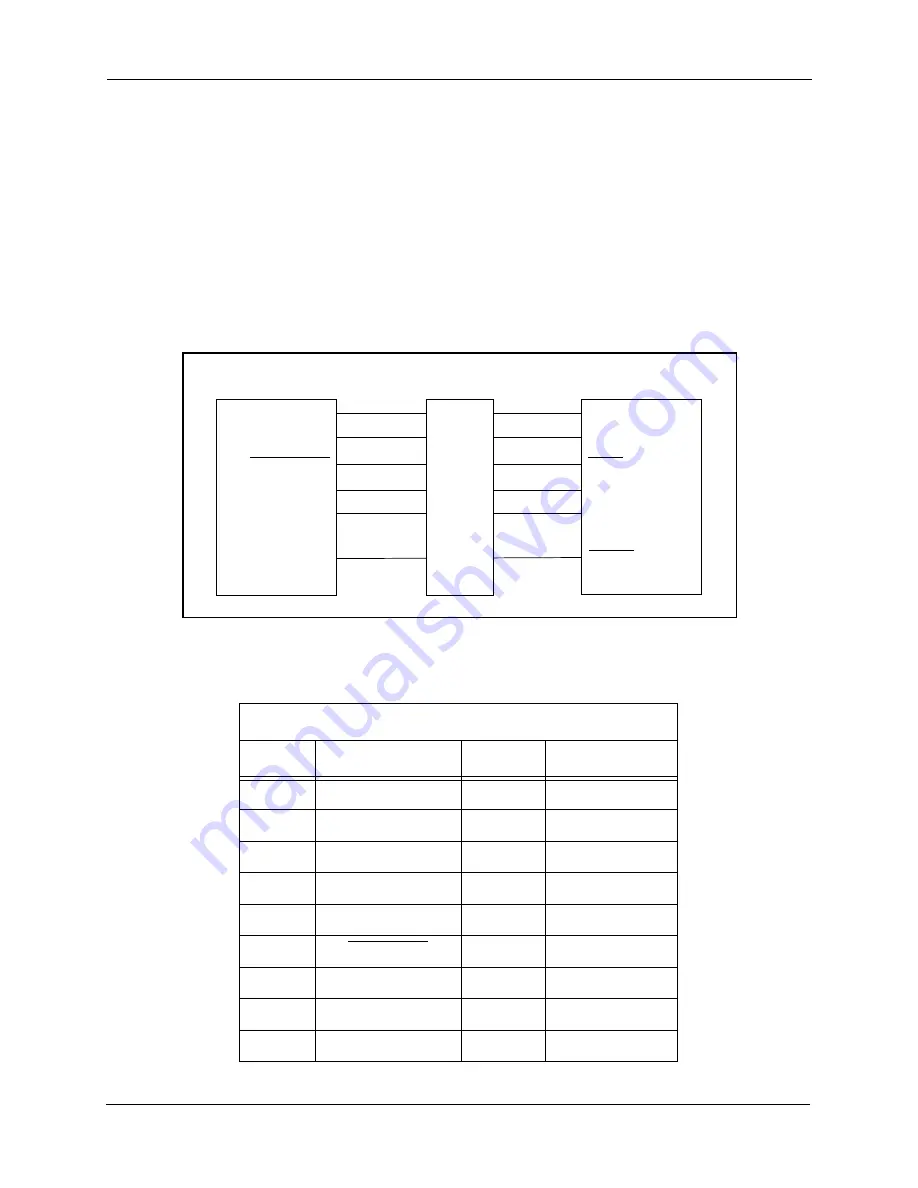
The Parallel JTAG Interface Connector, P1, allows the 56F805 to communicate with a
Parallel Printer Port on a Windows PC; refer to
. By using this connector, the
user can download programs and work with the 56F805’s registers.
pin-out for this connector. When using the parallel JTAG interface, the jumper at JG5
should be removed, as shown in
. A jumper, JG11, is provided to allow the
on-board Host/Target Interface to be powered by the Target board instead of the Host
system when necessary; reference
. This may be necessary when using a +3.3V
Host computer parallel port.
Figure 2-5. Block Diagram of the Parallel JTAG Interface
Table 2-5. Parallel JTAG Interface Connector Description
P1
Pin #
Signal
Pin #
Signal
1
NC
14
NC
2
PORT_RESET
15
PORT_IDENT
3
PORT_TMS
16
NC
4
PORT_TCK
17
NC
5
PORT_TDI
18
GND
6
PORT_TRST
19
GND
7
NC
20
GND
8
PORT_IDENT
21
GND
9
PORT_VCC
22
GND
PARALLEL JTAG
INTERFACE LOGIC
56F805
PORT_RESET
PORT_TCK
PORT_TMS
PORT_TRST
PORT_TDO
PORT_TDI
TDI
TDO
TRST
TMS
TCK
RESET
DB-25
F
re
e
sc
a
le
S
e
m
ic
o
n
d
u
c
to
r,
I
Freescale Semiconductor, Inc.
For More Information On This Product,
Go to: www.freescale.com
n
c
.
..


