2-14
56F805EVM Hardware User’s Manual
MOTOROLA
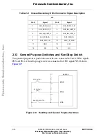
2.13 General Purpose Switches and Run/Stop Switch
Two general-purpose user push button switches are connected to Port D GPIO signals,
PD3 and PD4. A Run/Stop toggle switch is connected to GPIO signal PD5. Refer to
.
Figure 2-9. Run/Stop and General Purpose Switches
Table 2-9. Unused Secondary UNI-3 Connector Signal Description
J14
Pin #
Signal
Pin #
Signal
1
SU3_ZERO_X_A
2
SU3_ZERO_X_B
3
SU3_ZERO_X_C
4
SU3_BK_EMF_A
5
SU3_BK_EMF_B
6
SU3_BK_EMF_C
7
SU3_PHA_IS
8
SU3_PHB_IS
9
SU3_PHC_IS
10
SU3_I_S_DCB
11
GND
12
+5.0V
13
NC
14
NC
56F805
+3.3V
PD3
PD4
PD5
GP SWITCH 1
GP SWITCH 2
RUN/STOP SWITCH
+3.3V
+3.3V
F
re
e
sc
a
le
S
e
m
ic
o
n
d
u
c
to
r,
I
Freescale Semiconductor, Inc.
For More Information On This Product,
Go to: www.freescale.com
n
c
.
..


