Motor Protection Logic
MOTOROLA
Technical Summary
2-17
2.16.1 Primary UNI-3 Motor Protection Logic
The Primary UNI-3 DC Bus Over-Voltage signal is connected to the controller’s PWM
group A fault inputs. The three Primary UNI-3 Phase Over-Current signals are connected
to the device’s PWM group A’s fault inputs, i.e., FAULTA1, FAULTA2 and FAULTA3.
contains the diagram of the Over-Voltage and one phase of the Phase
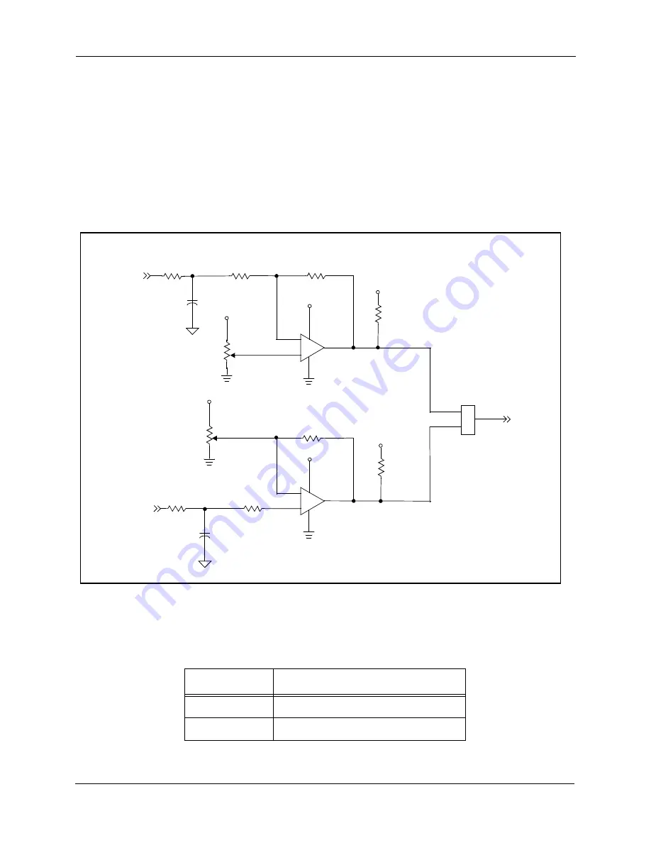
Over-Current circuit for the UNI-3 interface. The FAULTA1 input can be sourced from
the Phase A Over-Current circuit or the DC Bus Over-Current circuit. Jumper JG15
provides the selection; see
and
.
Figure 2-12. FAULTA1 Selection Circuit
Table 2-11. FAULTA1 Source Selection Jumper
JG15
Comment
1–2
Phase A Over-Current Sense input
2–3
DC Bus Over-Current Sense input
DC BUS CURRENT SENSE
I_sense_DCB
+
–
+5.0V
+5.0V
LM393
+3.3V
JG15
3
2
1
FAULTA1
+
–
+5.0V
+5.0V
+3.3V
PHA_IS
PHASE A CURRENT SENSE
LM393
F
re
e
sc
a
le
S
e
m
ic
o
n
d
u
c
to
r,
I
Freescale Semiconductor, Inc.
For More Information On This Product,
Go to: www.freescale.com
n
c
.
..

