background image

Motorola Vanguard

Device Management

Supports Management Module SM-MOT1000

Titlepae

Summary of Contents for 68390 - Vanguard 320 Router

Page 1: ...Motorola Vanguard Device Management Supports Management Module SM MOT1000 Titlepae ...

Page 2: ... www aprisma com manuals trademark list htm All referenced trademarks service marks and trade names identified in this document whether registered or unregistered are the intellectual property of their respective owners No rights are granted by Aprisma Management Technologies Inc to use such marks whether by implication estoppel or otherwise If you have comments or concerns about trademark or copy...

Page 3: ...Controls View 19 Data Compression Channel Statistics View 19 Encoder Queue Statistics View 21 Decoder Queue Statistics View 22 Motorola Configuration Applications MotConfigApps 22 CSIS Software Key and NUI Password Tables View 23 Software Key Table 23 NUI Password Table 23 Authorization Tables View 23 Software Authorization Table 23 Port Authorization Table 24 NS Channel Information View 24 Channe...

Page 4: ... Advertise Routes 54 Bridge Configuration Information View 54 Base Port Info 55 STP Port Info 55 Base Port Configurables 55 Local Termination Table View 57 Filtering Information View 58 MAC Address Filter Table 58 Protocol Filter Table 59 WAN Bridge Link Info View 59 Address Table Parameters View 60 802 1d Static Link Table View 61 SRB WAN Bridge Link Table View 62 Static Routes Info View 62 Stati...

Page 5: ...anslation Configuration Table View 110 Inbound 110 Outbound 111 Address 111 Motorola Vanguard Frame Relay Applications MotFRDTEApp and MotFRDCEApp 111 Frame Relay DTE Application 111 Port Configuration 111 Port Statistics 112 Station Configuration 112 Station Statistics 112 Model Information 112 Frame Relay DCE Application 112 Port Configuration Table 112 Port Statistics Table 112 Station Configur...

Page 6: ... M a n a g e m e n t Page 6 M o t o r o l a V a n g u a r d Port Statistics 121 Motorola Vanguard Frame Relay DCE DLCI Port Model 121 Information 122 Port Configuration 122 Port Threshold 122 Service Information 122 Port Statistics 122 INDEX 123 ...

Page 7: ... you to remotely monitor configure and troubleshoot Motorola Vanguard devices through software models in your SPECTRUM database Only information specific to the supported management module is included under this documentation topic For general information about device management using SPECTRUM and for explanations of basic SPECTRUM functionality and navigation techniques refer to the topics listed...

Page 8: ... access product optimized for branch offices that require consolidation of legacy traffic with LAN traffic over dedicated or switched X 25 Frame Relay point to point multipoint and ISDN circuits Motorola Vanguard 6560 MPRouter PRO This device extends the 6520 MPRouter capa bilities for large branch offices with higher throughput needs offering voice relay options for analog and digital voice appli...

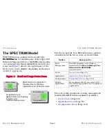
Page 9: ...on are listed below The rest of this document covering management module SM MOT1000 is organized as follows Device Views Page 10 Application Views Page 15 Configuration Views Page 114 Large Device icon Model Name Model Name Vanguard6455 Small Device icon appears in Topology Device Topology appears in Device Topology Location and Interface Device views Application and Container views Vanguard6455 O...

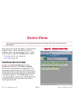
Page 10: ...MotMPRouter models Interface Device View Page 10 Port Icons Page 13 Interface Device View Access From the Icon Subviews menu for the MotMPRouter Device icon select Device Interface This view provides dynamic configuration and performance information for each of the device s serial network I O ports which are represented by Interface icons in the bottom panel of the view as shown in Figure 2 The mi...

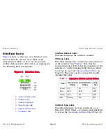
Page 11: ... 1 Note that the background color of the label also depends on the interface s current Administrative Status which is set by the user see Interface Status View on Page 13 This view can be accessed by double clicking this label Interface Type Label This label identifies the type of interface e g Ethernet FDDI Other etc Double click this label to access the Secondary Address Panel Page 13 ISO88023 M...

Page 12: ...ows you to modify field values IP Address Label This label displays the IP address for the interface Double click this label to open the Secondary Address Panel Page 13 which allows you to change the address and mask for this interface Interface Icon Subviews Menu Options Table 2 lists the Icon Subviews menu options available for the Interface icon Table 2 Interface Icon Subviews Menu Option Opens...

Page 13: ...his button allows you to select the desired operational state of the interface Valid values are On Off or Testing Secondary Address Panel Access From the Icon Subviews menu for the Interface icon in the Interface Device view select Secondary Address Panel This panel provides a table of IP addresses and masks obtained from the Address Translation table within the device s firmware You can change th...

Page 14: ...d the corresponding color for that status green if the port is up red if the port is down or in test mode Double click this label to open the Traps Events and Alarms Page 116 Port Statistics Displays the number of frames packets transmitted or received by this port since the last reset Double click this label to open the Port Performance View Port Label Icon Subviews Menu Table 3 lists the Icon Su...

Page 15: ...ce model is created SPECTRUM automatically creates models for each of the major and minor applications supported by the device The main Application view identifies all of these application models shows their current condition status and provides access to application specific subviews Figure 5 shows this view in the Icon mode If you prefer the List mode which displays applications as text labels s...

Page 16: ...cations documents are listed below Routing Applications Bridging Applications Transmission Applications MIB II Applications Technology Applications Device Specific Applications SPECTRUM imports the following device level proprietary MIBs into its database BCST OPT MIB BRIDGE OPT MIB CDX 6500 COMMON MIB DC OPT MIB DCP OPT MIB DSD OPT MIB FRDCE OPT MIB FRDCTE OPT MIB ISDN OPT MIB MX25 OPT MIB NS OPT...

Page 17: ...pps has a single minor application the Motorola Data Compression Application model typeMotDCApp The Icon Subviews menu for this application provides access to the following application specific subviews Data Compression General Statistics View Page 17 Data Compression Channel Statistics View Page 19 Data Compression General Statistics View Access From the Icon Subviews menu for the MotBWMgmtApp Ap...

Page 18: ...r of call requests rejected due to the unavailability of DC channels AggCRatio Ratio of incoming characters to outgoing characters for all DC channels over the past minute The following two buttons are located at the bottom of the Data Compression General Statistics view This button accesses both current and historical information about the encoder and decoder queues see Queue Statistics View Page...

Page 19: ...ther the statistics and the vocabulary history buffer for each channel will be automatically reset when the channel is active Column headings are described below Channel Number Index number identifying a particular channel Channel Status Indicates whether DC statistics will be automatically reset for this channel when it is active Possible values are reset or noreset History Buffer Indicates wheth...

Page 20: ... connection negotiating Source has accepted the Call Request and is waiting for a Call Accept from the destination node data passing Normal data passing state ap clearing Call Clear request arrived from access side np clearing Call Clear request arrived from network side clearing call A call collision or a Call Clear along with an X 25 reset or a start buffer discarding flushing on clr Call has be...

Page 21: ...accesses a view that lets you control statistics and history buffer reset parameters for individual DC channels see DC Controls View Page 19 Encoder Queue Statistics View Access In the Data Compression Channel Statistics view click the Encoder Queue Statistics button This view contains a table of encoder queue statistics for individual DC channels Column headings are described below ChanNo Index n...

Page 22: ...ressed mode to anti expansion mode AEFrames Number of anti expansion frames received AEstatus Indicates whether anti expansion mode is on or off BadFrames Number of decoded frames detected by the decoder that have been corrupted This includes frames with bad headers BadHeaders Number of decoded frames detected by the decoder that have a bad header PktDiscard Number of packets discarded while proce...

Page 23: ... on the modeled device It contains the following two tables Software Key Table Page 23 NUI Password Table Page 23 Software Key Table This table displays key values for optional software Entries are numbered sequentially starting with 1 NUI Password Table This table lists the Network User Identification NUI password for each user account and specifies which entry in the PAD Prompt Table is used as ...

Page 24: ...titutes unauthorized usage NS Channel Information View Access From the Icon Subviews menu for the MotNSApp Application icon select NS Channel This view lets you initiate and monitor channel information for the modeled device The view has the following two defined areas Channel Configuration Page 24 Channel Statistics Page 25 Channel Configuration This section displays the following information Num...

Page 25: ... this entry depends on the configured value of the Maximum Switch Service Entry parameter in the Node record up to a maximum of 1024 entries If this value is 0 no switched Service backup links may be configured i e this table will be empty Destination A unique name that identifies this entry Monitored Port The X 25 port to be monitored for link failure This is the port whose calls are rerouted in ...

Page 26: ...eparator 4 P or p Dialing to be continued in PULSE mode T or t Dialing to be continued in DTMF mode Flash To have the modem dial one of its pre programmed telephone numbers enter n where n identifies the pre programmed telephone number stored in the modem Act Mode This specifies how the switched service backup port will be activated Table 6 displays the activation modes and descriptions Deact Mode...

Page 27: ...mpts Security This specifies under what conditions the port channel authorizes call request Table 8 displays the security channel and descriptions Table 7 Deactivation Modes Mode Description none Backup port can only be deactivated by operator intervention busyout The backup port is deactivated after all the calls on that port are cleared for a predetermined amount of time This substitutes the val...

Page 28: ...stics Table View Access From the Icon Subviews menu for the MotSSApp Application icon select Restoral Port Statistics This view lists the statistics parameters for the Switch Service Link Backup port station and channel Column headings are as follows Port No The backup port number used as an index to access Switched Service LBU statistics Port Type The port type of the backup port Table 8 Security...

Page 29: ...DialedNo The phone number dialed the last time the backup port was activated Port Statistics Table View Access From the Icon Subviews menu for the MotSSApp Application icon select Link Statistics This view lists the statistics parameters for the Link Backup s monitored port The view has the following two defined areas Monitored Port Page 29 Calling ID Page 30 Monitored Port This section displays t...

Page 30: ...n the record Call String Each calling id entry is a numeric value which may contain periods or dashes Only calls matching these ids will be allowed when calling id security is enabled TFTP Statistics View Access From the Icon Subviews menu for the MotTFTPApp Application icon select Statistics This view lets you initiate and monitor TFTP file transfers to and from the modeled device The view has th...

Page 31: ... of bytes transferred This value is dynamically updated during a transfer Status The current or final status of the transfer operation SVC Calls Table View Access From the Icon Subviews menu for the MotVCApp Application icon select SVC Calls Table This view lets you view the Switched Virtual Circuit SVC calls Column headings are as follows Index Position in the list of SVCs Calling Channel Calling...

Page 32: ... other parameters in the record PVC Source The PVC source channel identifier See Table 10 for codes and descriptions PVC Destination The PVC destination channel identifier Route Selection Configuration Table View Access From the Icon Subviews menu for the MotVCApp Application icon select Route Selection Table This view allows you to set up the route selection configuration Column headings are as f...

Page 33: ... a combination of priority and load conditions 0 is the backup port Values 1 15 are also valid 1 being the highest priority and 15 the lowest LAN Connection Configuration Table View Access From the Icon Subviews menu for the MotWANApp Application icon select LAN Configuration This view contains the Configuration parameters for each LAN Connection Column headings are as follows ConnNo A specific LA...

Page 34: ...ing accounting records will be created for calls on this LAN Connection Table 12 displays the valid options and descriptions TrafficPriority The Traffic Priority of this LAN Connection Valid values are low med high exp Expedite Priority nc and newvalLow same as low ConnQueue The maximum number of bytes that will be queued for this LCON before transmission on the WAN link It is recommended that thi...

Page 35: ...al destination A setting of 0 causes this parameter to be ignored MaxSVC The maximum number of parallel connections that can be established to the remote destination Parallel SVCs are established when congestion thresholds are reached on active connections Threshold The number of outstanding data bytes that will trigger the establishment of a Parallel SVC If this number of data bytes has been tran...

Page 36: ... on the WAN in bytes PktQueued The current number of packets queued awaiting transmission on the WAN MaxQueue The maximum number of packets queued awaiting transmission on the WAN TimeMaxQueue The date and time when the number of packets queued awaiting transmission on the WAN reached its maximum AvgPktSizeRcv The average size of the packets received on the WAN PktDisDelay The number of packets di...

Page 37: ...n headings are described below ConnNo A specific LAN Connection Record ConnType Specifies whether the connection is a Permanent Virtual Circuit PVC or a Switched Virtual Circuit SVC Encap This parameter specifies the data encapsulation type used over this LAN Connection Valid values are codex rfc1294 rfc877 and newvalCodex same as codex ConnStat The current state of the PVC or a SVC Table 13 displ...

Page 38: ...lear packet last received by the LAN connection and explains why the last call was cleared SVCEstab Count of parallel SVCs with calls established MaxSVCNo Number of Parallel SVCs Packet Information Access In the Data Summary Statistics view click the Packet Statistics button This view contains a table of packet statistics for LAN Connections Column headings are described below ConnNo A specific LA...

Page 39: ...rReqRc The total number of Clear Request Packets received from the WAN ClearConfTx The total number of Clear Confirm Packets sent on the WAN ClearConfRcv The total number of Clear Confirm Packets received from the WAN ResetReqTx The total number of Reset Request Packets sent on the WAN ResetReqRcv The total number of Reset Request Packets received from the WAN ResetConfTx The total number of Reset...

Page 40: ...ication specific views MotBridgeApp Bridge Statistics View Page 40 Bridge Configuration Information View Page 54 MotRouterApp ARP Cache Table View Page 50 IP Access Control Table View Page 51 IP Interface Table View Page 52 Static Routes Info View Page 62 IP Interchange Table View Page 64 Filter Gateway Priority Info View Page 65 IP BOOTP Server Info View Page 67 Bridge Statistics View Access From...

Page 41: ... Statistics view This button accesses a table providing statistical information for each bridge link associated with the device s transparent bridging function see Transparent Bridge Link Stats Table View Page 42 This button accesses a table providing statistical information for each port associated with the device s transparent bridging function see Transparent Bridge Port Stats Table View Page 4...

Page 42: ...each of the device s WAN Bridge Links see WAN Bridge Link Stats Table View Page 49 This button accesses a table providing traffic statistics broken down by frame type for Local Termination sessions see Local Termination Stats Table View Page 49 Transparent Bridge Link Stats Table View Access In the Bridge Statistics view click the Transparent Bridge Link Stats button This view contains a table pro...

Page 43: ...MulticastRx The number of Multicast Frames received on this WAN Bridge Link MulticastTx The number of Multicast Frames transmitted on this WAN Bridge Link BroadcastRx The number of Broadcast Frames received on this WAN Bridge Link BroadcastTx The number of Broadcast Frames transmitted on this WAN Bridge Link InBoundDisc The number of frames discarded due to receive Link State not being set to forw...

Page 44: ...received on this LAN link MulticastTx The number of Multicast Frames transmitted on this LAN link BroadcastRx The number of Broadcast Frames received on this LAN link BroadcastTx The number of Broadcast Frames transmitted on this LAN link InboundDisc The number of frames discarded due to Receive Link State not being set to forwarding OutboundDisc The number of frames discarded due to Receive Link ...

Page 45: ... a bridge link takes upon receiving a frame Possible values are blocking listening learning forwarding and broken LinkStatus The status of the bridge link Valid values are enable or disable PathCost The contribution of this bridge link to the path cost towards the spanning tree root that includes this bridge link DesignatedRoot The unique Bridge Identifier of the Bridge recorded as the Root in the...

Page 46: ...sRx The Port Identifier of the bridge link on the Designated Bridge for this bridge link s segment FramesTx The number of times this port has transitioned from the Learning state to the Forwarding state RingNo The number of times this port has transitioned from the Learning state to the Forwarding state SRB WAN Bridge Link Stats View Access In the Bridge Statistics view click the SRB WAN Bridge Li...

Page 47: ...discarded by this bridge link because the routing descriptor field contained an invalid adjacent segment value DupSegDisc The number of frames that have been discarded by this bridge link because the routing descriptor field contained a duplicate segment identifier HopCountExcDisc The number of explorer frames that have been discarded by this bridge link because the Routing Table 15 Spanning Modes...

Page 48: ...n a port by port basis Column headings are as follows Port No Number identifying a particular port SrcAddrFiltIn The number of inbound frames on this port that were not forwarded because of Source MAC Address filtering SrcAddrFiltOut The number of outbound frames on this port that were not forwarded because of Source MAC Address filtering DestAddrFiltIn The number of inbound frames on this port th...

Page 49: ...ridge that might share the same IFIndex For example in the case where multiple ports correspond one to one with multiple X 25 virtual circuits this value might identify an e g the first object instance associated with the X 25 virtual circuit corresponding to this port LinkStatus Current status of the WAN Bridge Link Possible values are listed in Table 14 Link Status Descriptions on Page 41 LastSt...

Page 50: ...tted TotFrInData The sum of Data Frames Receiver Ready Receiver Not Ready Reject SABME and ID Exchange frames received TotFrOutData The sum of Data Frames Receiver Ready Receiver Not Ready Reject SABME and ID Exchange frames transmitted StatsBoot This command is used to boot a Local Termination session when set to Boot ARP Cache Table View Access From the Icon Subviews menu for the MotRouterApp Ap...

Page 51: ...n IP address IP Protocol number range and TCP UDP port number range all match the packet SourceAddr IP source address to compare against a received packet s source IP address field Matches are determined in conjunction with SourceAddMask SourceAddrMask This value is logically AND ed with SourceAddr and compared with the Source Address of a received packet For example a mask of 255 0 0 0 with a res...

Page 52: ...for FTP 23 for Telnet 25 for SMTP 513 for rlogin 520 for RIP Routing Information Protocol and 600 for X IP Interface Table View Access From the Icon Subviews menu for the MotRouterApp Application icon select IP Interface Table This view contains a table of IP router interface information Column headings are described below Heading names prefixed by Advt are contained in a subview accessed via the ...

Page 53: ...LearnSubnetRte This setting enables disables the learning of new subnet level routes received from neighboring routers on this interface s network AcceptRIP This setting enables disables the processing of RIP updates received on this interface ASNo The Autonomous System AS number to be used as a tag for RIP information received on this interface Tags are used to group routes together for later rea...

Page 54: ...are as follows AdvtDefRte Enables disables advertising the default route of 0 0 0 0 on this interface AdvtNetworkRte Enables disables advertising directly attached networks and learned IP network routes on RIP updates transmitted on this interface AdvtSubnetRte Enables disables the inclusion of all subnet routes within RIP updates sent on this interface AdvtStatic DirectRte Enables disables the in...

Page 55: ...s path trace function and in IP tunneling for Token Ring networks Max Bridge Links The maximum number of bridge links that will be allowed STP Port Info This area of the Bridge Configuration Information view displays the following settings Stp Control Auto indicates that the bridge participates in STP and automatically calculates the STE Single Route Broadcast frame path Man indicates the spanning...

Page 56: ...llowing six buttons are located at the bottom of the Bridge Configuration Information view This button accesses a table providing traffic statistics broken down by frame type for Local Termination sessions see Local Termination Table View Page 57 This button accesses a table providing traffic statistics broken down by frame type for Local Termination sessions see Filtering Information View Page 58...

Page 57: ...a frame received from the WAN for the session to be spoofed SAP The SAP Service Access Point of the station This value must match the source SAP of the frame received from the LAN port or destination SAP of a frame received from the WAN for the session to be spoofed ProfileName The name of the local termination profile configured for this station see LIcName below This name is used to obtain the a...

Page 58: ... down inoperative TxWindSize The maximum number of I frames a station may transmit without acknowledgment Filtering Information View Access In the Bridge Configuration Information view click the MAC Address Filtering button This view contains the following two tables MAC Address Filter Table Page 58 Protocol Filter Table Page 59 MAC Address Filter Table This table appears in the upper half of the ...

Page 59: ... apply to all bridge links Acknowledge Timer The length of time in seconds after which the link station will determine a remote station has failed to acknowledge an outstanding I frame or supervisory frame with poll bit set to 1 Receive Ack Timer The length of time in tenths of seconds that the link station will wait to acknowledgment a frame from a remote station This is a method of reducing the ...

Page 60: ...g employed on this link AddrFiltAction Determines whether the link will pass or block frames with a MAC address that are not listed in the MAC Address Filter Table A setting of none indicates no MAC address filtering will be performed for this link ProtFiltAction Determines whether the link will pass or block frames with a Protocol value that are not listed in the Protocol Filter Table A setting o...

Page 61: ...h a frame must be received in order for this entry s filtering information to apply A value of zero indicates that this entry applies on all of the device s bridge links for which there is no other applicable entry FwdFrmToLnk The set of WAN bridge links to which frames received from the specified port and destined for the specified MAC address can be forwarded EntryStatus The current status of th...

Page 62: ... link port is considered to be connected to by the bridge A value of 65535 signifies that no target segment is assigned to this port LargestFrame The maximum size of the INFO field LLC and above that this port can send receive Static Routes Info View Access From the Icon Subviews menu for the MotRouterApp Application icon select Routing Information This view contains the following three areas Stat...

Page 63: ...rol table for this router Internal NetMask This IP Address overrides the Router ID to become the default IP address for the router The default IP address is used as the IP source address of PING and ICMP frames originated from the router IP address is reported in SNMP trap frames If both Router ID and this internal IP address are left undefined as 0 0 0 0 the default IP address is the IP address o...

Page 64: ...NMP Trap PING and other ICMP frames originated from the router If both the Router ID and Internal NetMask are left undefined as 0 0 0 0 the default IP address is the IP address of the lowest numbered operational interface of the router Advertised Default Hops The cost metric usually the number of hops that RIP will advertise for the default route of 0 0 0 0 A metric of 16 advertises that the defau...

Page 65: ...ric A configured cost of the route to the interior network interpreted as a hop count This cost is reported to EGP if IGPMetric is off Input Table This area of the IP Interchange Table view has the following column headings Index Number identifying a particular input route NeighAS A neighboring AS to which route information will be readvertised via OSPF and RIP A value of 0 adds the route to the d...

Page 66: ...rity Info view has the following column headings Index Number identifying a particular filter DestIPAddr IP address of a network subnet to filter All packets destined for a filtered network are discarded and no route to the filtered network is advertised AddrMasks Network or subnetwork address mask associated with the network subnet address to filter Default Gateway Table This table within the Fil...

Page 67: ...ions to obtain their startup operating system software and other parameters from a BOOTP server host on the IP network Bootp Max Hops The maximum cost metric hop count a BootP request is allowed to attain before being discarded Bootp Idle Time sec The number of seconds the router will wait for a BOOT request to be repeated before forwarding the request to BOOTP Server Motorola Node Management Appl...

Page 68: ...eneric trap Last Trap Info The interesting information portion of the last trap PDU issued by the SNMP Agent Node Configuration View Access From the Icon Subviews menu for the MotNodeMgmtApp Application icon select Node Configuration This view and a continuation accessed via the More button at the bottom of the view provides node configuration information in the following areas General Node Inform...

Page 69: ...mber of calls eliminates data loss in extreme traffic conditions A value of zero indicates unlimited calls Time Stamp The node time in hh mm ss format used for time stamps of events and traps No of Broadcast Networks The number of Broadcast Networks to which this node can send broadcast messages A value of zero means the broadcast function is disabled for this node Broadcast Port Subaddress The br...

Page 70: ... non diagnostic functions above which an alarm will be generated Port Error Threshold The number of port errors such as parity or framing errors that can be detected before a medium severity alarm is generated Alarms This area of the Node Configuration view displays the following alarms settings Alarm Distribution Specifies where alarm and event reports will be sent Possible values are none if no ...

Page 71: ... minutes The number of minutes billing records are stored before they are automatically sent to a logging device for printing PVC Billing Record Timer minutes The number of minutes billing records for PVCs with billing activated are stored before they are automatically sent to a logging device for printing General Product Feature Set Identifies a general class of feature set for the product PAD Bu...

Page 72: ... in call packets on X 25 links with the INL option for network routing This should be the same in all nodes in the network It need only be changed if it interferes with some other private network facility DCP Facility Code This value is used in call request and call accept packets on X 25 links to carry DCP information at call setup and reconnection time The code must be the same for all nodes in ...

Page 73: ...atistics view displays the following information Current number of PVC connections The number of permanent virtual circuit connections currently in place Max PVC connections since last reset The highest number of permanent virtual circuit connections in place since the last reset Reset Buttons This area of the Node Statistics view contains the following information Reset All Statistics Toggling th...

Page 74: ...t Number of Calls sec Max no of calls sec This button accesses a table that lists all of the node s ports and allows statistics to be reset on a port by port basis This button accesses a subview providing the following throughput statistics for the node Current characters sec Current packets sec Max characters sec since last reset Max packets sec since last reset Board Statistics View Access From ...

Page 75: ...MgmtApp Application icon select Port Statistics This view contains a table of statistical information about the modeled device s ports Three buttons at the bottom of the view access separate tables for receive transmit and error statistics Column headings for the main table are as follows PortNo Identifies a particular port on the modeled device PortType The type of port Valid values are illegal n...

Page 76: ...stics for each port Port Utilization of bandwidth being used Total Characters Sent Total Packets Sent Total Frames Sent Average Characters Sent per second Average Packets Sent per second Average Frames Sent per second This button at the bottom of the Port Statistics view accesses the Port Errors table which provides the following statistics for each port Overrun Errors Underrun Errors CRC Errors P...

Page 77: ... Table View Page 92 Voice Port Configuration Table View Access From the Icon Subviews menu for the MotVoiceApp Application icon select Port Configuration This table contains the port configuration parameters to configure the DSPM E M DSPM FXS DSPM HC and DSPM SM The following column headings are displayed PortNumber The voice port number PortType The port type A value of voice signifies this is a ...

Page 78: ...pe based on country Table 19 displays the valid filters This parameter is displayed for DSPM FXS and skipped for DSPM E M DSPM HC FXO and all virtual port types HybridEAndM2 Hybrid balance filters and termination type based on country Only for E M 2wire interfaces Table 20 displays valid filters and descriptions Table 19 Hybrid FXS Filters Filter Description sixHundred 600 ohm interface for USA Ja...

Page 79: ...le 21 Signalling Mode signalling Mode Description normal Allows signalling to pass end to end and signalling will be used to control circuit state and packet flow node A permanent voice path is established and packet flow is always enabled but no signalling will be passed through nc Skipped during configuration Table 22 Signalling Control Transmission Mode Description immediate Digits are transmit...

Page 80: ...ontrol Select if the Digital Speech Interpolation Silence Detector will be used with this channel Valid values are enabled disabled and nc SmoothingDelay Select maximum inter packet arrival jitter due to network in milliseconds EchoControl Select echo control Valid values are disabled enabled and nc This parameter will be skipped in normal mode and only displayed when DEBUG is turned on EchoReturn...

Page 81: ...he signal by that many dB Entering Table 25 E M Interface Type Type Input Signal Level 4 Wire 600 7 0 to 16 0dbm 2 Wire 600 7 0 to 16 0dbm 2 Wire UK 5 0 to 16 0dbm 2 Wire Germany 5 0 to 16 0dbm Virtual Ports 100 and above 8 0 to 6 0dbm Table 26 FXO Interface Type Type Input Signal Level 600 Ohms 0 0 to 8 0dbm 600 Ohms Adaptive 0 0 to 8 0dbm Table 27 FXS Interface Type Type Input Signal Level 600 O...

Page 82: ...call It consists of 0 8 alphanumeric characters CallControl Select calling method Table 29 displays the valid methods and descriptions AutoCallTimeout Time interval between two successive calls in case of failure of previous call Used only in Auto call control mode This parameter will be skipped if CallControl is Offhook or Switched CallRetries Enter maximum number of call retries when previous ca...

Page 83: ...state that represents the idle state For E1 ports and T1 ESF ports these bits represent the ABCD signalling bits on the interface For T1 SF ports these bits represent ABAB signalling bits The range is from 0000 to 1111 T1E1RxActiveOff The signalling state that represents the active state For E1 ports and T1 ESF ports these bits represent the ABCD signalling bits on the interface For T1 SF ports th...

Page 84: ...quent receive digit before declaring a misdial Granularity is 1 second TxWinkDelay The time delay from receiving a valid Offhook state to start transmitting a wink Granularity is 10 milliseconds TxWinkWidth The width of the transmitted wink pulse Granularity is 10 milliseconds TxDigitDelay The time delay before transmitting the first DTMF digit after a wink is received Granularity is 10 millisecon...

Page 85: ...ed by the T1 E1 Rx Idle on hook State parameter RxCalledEndDisc The additional amount of time beyond the Rx Disconnect filter the calling end must be Onhook to disconnect a call Granularity is 1 second LineErrorRecove The length of time voice will be suppressed after LOS or OF condition clears Granularity is 10 milliseconds This parameter will be displayed for virtual ports only signallingSample T...

Page 86: ... idle state disconnect and maintains the voice call in the answered state Time is entered in minutes TrsprntSingalin The received signalling state that represents the Busyout state For E1 ports and T1 ESF ports these bits represent the ABCD signalling bits on the interface For E M analog ports Offhook is assumed for the busyout alarm state The range is 0000 to 1111 XlateSig0000Fro XlateSig1111Fro ...

Page 87: ...dial tone DialLwFreAmplit The amplitude of the lower frequency to generate the dial tone To be specified in steps of 0 5dB 30dB turn off output The range is from 30dBm to 3dBm DialupoFre The higher of the two frequencies needed to generate the dial tone DialUpFreAmplit The amplitude of the upper frequency to generate the dial tone To be specified in steps of 0 5dB 30dB turn off output The range is...

Page 88: ... The lower of the two frequencies needed to generate the Fast Busy tone FastBusyLwFreAm The amplitude of the lower frequency to generate the Fast Busy tone To be specified in steps of 0 5dB 30dB turn off output The range is from 30dBm to 3dBm FastBusyUpFre The higher of the two frequencies needed to generate the Fast Busy tone FastBusyUpFreAm The amplitude of the upper frequency to generate the Fa...

Page 89: ...ar Forward or Clear Back pulse in msec RxMinSlaveClear The minimum pulse width to declare a valid received Slave Clear Forward or Clear Back RxMaxSlaveClear The maximum pulse width to declare a valid received Slave Clear Forward or Clear Back TxSlaveRelease The width of the transmitted Slave Release Guard pulse in msec RxMinSlaveRelea The minimum pulse width to declare a valid received Slave Relea...

Page 90: ...w contains the following information RxDTMFDigitS Select the voice number plans for the 6520 6560 network The received DTMF digits received by the voice interface is compared to this parameter Enter a trailing asterisk as a wild card Use the space bar to blank the parameter Range 1 to 20 characters valid characters are 0 through 9 and The characters and are allowed only for ease of reading They ar...

Page 91: ...ed The character R is used to separate the prefix digit string from the postfix digit string The maximum number of digits that can be sent to the remote end is 16 PostFixDigits Select DTMF digits to be added at the end of the received DTMF stream before sending the digit stream to the remote port Range 1 to 20 characters valid characters are 0 through 9 and P The characters and are allowed only fo...

Page 92: ...er indicates whether the 48 volt power supply is installed in the node Valid values are none present and na This parameter will not be displayed for DSPM HC PortState The status of the port Valid values are enable and disable CircuitState The state of the SVC associated with this port Valid values are connected and disconnected CurrentMode The current operating mode of the DSP Valid values are voi...

Page 93: ... of times receive packets were dropped due to network overload or processor loading DroppedPacket The estimate of packets dropped end to end in the network DSPInternalFa The number of recoverable software faults It is displayed only when the DEBUG flag is set TxPackets The number of packets received from the network port since the last reset RxPackets The number of packets sent to the network port...

Page 94: ...apMac The voice signalling state machine state is an 11 character field representing the state of the signalling software PPSTsignallingSeqTrapTim The time from the previous state to this state measured in milliseconds PPSTsignallingSeqTrapCom The comment field is an ASCII string up to 16 characters long CurrentStatus This is the call processing state machine status Valid values are inhibited disc...

Page 95: ...llingA The calling address present in the last inbound call packet InCallPckFaci The facilities present in the last inbound call packet InCallPckCUD The call user data present in the last inbound call packet OutCallPckCal The called address present in the last outbound call packet OutPckCalling The calling address present in the last outbound call packet OutCallPckFac The facilities present in the...

Page 96: ...his major application model type MotWANApps has two minor applications model types MotT1E1App and MotX25App The Icon Subviews menu associated with this application provides access to the following application specific views MotT1E1App Virtual Port Mapping Table Page 96 MotX25App X 25 Configuration Table View Page 98 X 25 Statistics Table View Page 106 Translation Configuration Table View Page 110 ...

Page 97: ...port type data it is 56K or 64K the default being 56K and nc PhyIntfact Selects the type of physical interface for the Virtual Port Valid values are t1e1 the physical interface is a T1 or E1 card so the physical interface is a SO card and nc SOPortNo The port number of the SO interface this virtual port is associated with A value of 0 implies that this parameter was skipped during configuration B ...

Page 98: ...d types X 25 Configuration Table View Access From the Icon Subviews menu for the MotX25App Application icon select Configuration Table This view contains a table that displays general configuration information about the device s X 25 ports Buttons at the bottom of the view access separate tables for PDN information and statistics Table 34 Network Specific Calls Feature Description none No network ...

Page 99: ...locking The highest available speed is dependent on the card type and the interface type Default value is 9600 Options Identifies any options in effect for this port Applicable codes and descriptions for X 25 ports Table 36 ConnType Codes Code Description simp Simple no control signals required dtr Dedicated requires the data terminal ready signal DTR dtrd Same as DTR except data set ready DSR dro...

Page 100: ...lled address from outbound calls DEGO Delete calling address from outbound calls REGI Replace calling address with configured Port Address in inbound calls REGO Replace calling address with configured Port Address in outbound calls HOLD Hold calls over link restart NRST Do not send restart packet on link up BKUP This is a backup port to be activated if other ports are down SRGI Select route by the...

Page 101: ...ics broken down by frame and packet type for each X 25 port see Packet Frame Statistics View Page 104 This button accesses a view that provides tables of logical channel and timer statistics for each X 25 port see Channel Statistics View Page 105 PDN Information View Access In the X 25 Configuration Table click the PDN Information Table button This table provides Public Data Network PDN informatio...

Page 102: ... of prefix digits that will be removed from the called address before forwarding the call to a PDN InDigStrip The number of prefix digits that will be removed from the incoming calling address before forwarding the call from a PDN SubAddrSize The number of digits in the subaddress of an X 25 address FacilSubcrip Identifies any facility subscriptions in effect for this port Applicable codes and des...

Page 103: ...bles the Idle Disconnect feature This feature may only be enabled on DIMO DIMOa DIMOb DIMOv SIMPv ports with the BKUP option selected Security For V 25bis backup ports the type of call security to use prior to the link being detected up if value is disable both incoming and outgoing calls are allowed if enable only outgoing calls are allowed and incoming calls will be immediately terminated This p...

Page 104: ...ics button This view contains a table that provides packet and frame information for each of the device s X 25 ports Column headings are as follows PortNo Identifies a particular X 25 port InitFrame Indicates the kind of frame sabm or disc required by other end for link startup If value is none the link is initiated by the other end FmNumbering Indicates whether port uses normal norm or extended e...

Page 105: ... maximum number of logical channels that can be used for Permanent Virtual Circuits PVCs on this X 25 link The total number of PVC and SVC Switched Virtual Circuit channels on a link should be kept as small as possible and consistent with needs PVC connections must be configured in the PVC Table StartPVCChan The starting logical channel number for the PVCs on this link Not used if MaxPVCChan is ze...

Page 106: ...stics Column headings for the general statistics are as follows PortNo Identifies a particular X 25 port Status Current status of the port Valid values are up down disabled and busy out State Code indicating the current state of the port as shown in the Table 39 Speed The speed of the port when clocking is internal or the detected clock speed if clocking is external UtilIN Percentage of port bandw...

Page 107: ...ble view click the ISDN Call Status button This view contains a table that provides ISDN call statistics for each X 25 port These statistics are only valid for virtual switched data ports Column headings are as follows PortNo Identifies a particular X 25 port NumRx The number of inbound calls that were attempted since the last statistics reset RxReject The number of inbound calls that were rejecte...

Page 108: ...since the last statistics reset TxLastFail Code indicating the reason the last inbound call was rejected see Table 40 for descriptions TxLastNum The phone number of the virtual port of the last ISDN call made from this port TxMinDur The shortest duration of any outbound ISDN call from this port since the last statistics reset TxMaxDur The longest duration of any outbound ISDN call from this port s...

Page 109: ...econd being sent by the port OverrunErr Number of overrun errors since the last node or statistics reset UnderrunErr Number of underrun errors since the last node or statistics reset Packet Info The Packet Information table within the Data Statistics view has the following column headings InPkts Number of packets received since last node port or statistics reset OutPkts Number of packets sent sinc...

Page 110: ...t or statistics reset InRNR Number of frames received since last node port or statistics reset indicating RNR OutRNR Number of frames sent since last node port or statistics reset indicating RNR InRR Number of frames received since last node port or statistics reset indicating RR OutRR Number of frames sent since last node port or statistics reset indicating RR InREJ Number of frames received sinc...

Page 111: ...orwarding calls to a PDN Options If value is olda the original called address is inserted into outbound call user data Otherwise value is none Address This section displays the following information InSubAddr The subaddress contained in an inbound call from another network usually a PDN It will be translated into a private network address before the call is forwarded PrivNetAddr The private networ...

Page 112: ...jects from the Motfrdte_Mib s Frame Relay DTE Station Statistics Table which contains statistical parameters for the Frame Relay DTE Station table Model Information This opens the Model Information view for the application model For more information on this view see SPECTRUM Views 2517 Frame Relay DCE Application The MotFRDCEApp has the following views available from the Icon Subviews menu Port Co...

Page 113: ...me Relay DCE Station table Station Statistics Table This option displays the DCE Station Table Statistics view This view shows the value of objects from the Motfrdce_Mib s Frame Relay DCE Station Statistics Table which contains statistical parameters for the Frame Relay DCE Station table Model Information This opens the Model Information view for the application model For more information on this ...

Page 114: ...odels of Motorola Vanguard devices Device Configuration View Page 114 Interface Configuration View Page 115 Device Configuration View Access From the Icon Subviews menu for the MotMPRouter Device icon select Configuration This view Figure 6 provides status and configuration information about the device as a whole as well as on a port by port basis It also provides button access to an Interface Add...

Page 115: ... Admin Status The desired operational state of the interface Valid values are On Off or Testing Last Change The System UpTime value when the interface entered its current operational state IP Address Network Mask This window provides a list of the user defined names and IP addresses for the interface Physical Address The Ethernet MAC address of the interface Bandwidth The estimated bandwidth of th...

Page 116: ... Page 116 Vanguard 6400 and 6500 Trap Support Page 118 Standard Trap Support The following standard traps are supported for Vanguard 300 320 6400 and 6500 devices Vanguard 300 320 Trap Support The supported device specific traps for Vanguard 300 320 devices are listed in Table 42 Page 117 In the OID column of this table model should be replaced with the model number of the Vanguard device i e 300 ...

Page 117: ... 7 0x02580015 None node boot for rout tables 1 3 6 1 4 1 449 2 1 model 6 16004 1 3 6 1 4 1 449 2 1 1 1 7 0x0258000d 0x0258000d Orange node boot for pvc 1 3 6 1 4 1 449 2 1 model 6 16005 1 3 6 1 4 1 449 2 1 1 1 7 0x0258000e 0x0258000d Orange port util exceeded 1 3 6 1 4 1 449 2 1 model 6 17000 1 3 6 1 4 1 449 2 1 1 1 7 0x02580003 0x02580003 Yellow cpu util exceeded 1 3 6 1 4 1 449 2 1 model 6 17002...

Page 118: ...le the SEVERITY comment is used to determine which event should be generated for the the trap Based on severity each trap will be mapped to one of five unique events Table 43 The code power supply down trap is CRITICAL so we will generate the 0x2580050 event which is defined as critical and will result in an alarm Table 43 Vanguard 6400 Events Unique Event Generated Event Severity Event or Alarm G...

Page 119: ...TEDLCI and MotDCEDLCI are the sub interface model types that allows you to manage Data Terminal Equipment DTE and Data Circuit Terminating Equipment DCE DLCI ports on Motorola Vanguard devices The MotFRDTEAPP and MotFRDCEApp model types are available when the Motorola Vanguard management module is installed See the Motorola Vanguard Frame Relay Applications MotFRDTEApp and MotFRDCEApp Page 111 sec...

Page 120: ...ging Frame Relay Networks section of the Frame Relay Manger User Guide 2102 Information This view allows you to set polling and logging information for the port model It is possible to configure SPECTRUM to poll DLCI ports at regular intervals When SPECTRUM polls these ports it captures the values of various external MIB objects You can choose to log these values and use them for monitoring and an...

Page 121: ...e purposes only Port Statistics The Port Statistics view is not available from the Frame Relay Manger DLCI_Port model type It shows statistics for this DTE port from the Cdx6500SPSTFRDCEStation table of the the vanguard 65xx frdce mib Motorola Vanguard Frame Relay DCE DLCI Port Model The MotDCEDLCI is a sub interface model type which represents the DCE DLCI ports on Motorola Vanguard devices The f...

Page 122: ...fic to the DCE that the port represents Port Threshold The Port Threshold view establishes levels of activity that will generate alarms Service Information The DLCI_Port Service Information view provides information about service providers associated with the frame relay network All service information is entered manually and is provided for reference purposes only Port Statistics This view is not...

Page 123: ...7 Application Device specific 17 MotBridgeApp 40 MotCSISApp 22 Motorola Bandwidth Management Applications MotBWMgmtApps 17 Motorola Configuration Applications MotConfigApps 22 Motorola Data Compression Application MotDCApp 17 Motorola LAN Applications MotLANApps 40 Motorola Node Management Application MotNodeMgmtApp 67 Motorola WAN Applications MotWANApps 96 Motorola X25 Application MotX25App 96 M...

Page 124: ...ype 69 ClockSource 99 ClockSpeed 99 Codex Group Facility 72 Codex Proprietary Information 72 Codex Proprietary Protocol ID 72 Colors Interface Status Label 11 Configuration views 114 ConnRejects 18 ConnType 99 Control Port Subaddress 69 CPU Utilization Threshold 70 CPUutil 75 CRC Errors 76 Ctrl Port Idle DisconnectTime 69 Current number of PVC connections 73 CurrentSVC 107 D Data Compression Chann...

Page 125: ...76 FrRejIn 50 FrRejOut 50 FrRnrIn 50 FrRnrOut 50 FrRrIn 49 FrRrOut 50 FrSabmeIn 50 FrSabmeOut 50 FrXidIn 50 FrXidOut 50 FwdTransition 45 G General Node Information 68 General Product Feature Set 71 Generic Traps Type 68 H History Buffer 19 HopCountExcDisc 47 I I FNo 52 I FType DIM1 77 I FType DIM2 77 Icon Subviews Menus for Interface icon 12 for Port label 14 Icons Device 9 Interface 11 IFIndex 49...

Page 126: ...ink Stats 41 LinkCkt 49 LinkNo 42 45 46 49 LinkState 45 LinkStatus 45 49 Local Termination Stats Table View 49 Local Termination Table View 57 M MAC Address Protocol Filtering Stats Table View 48 MacAddr 51 Max Billing Records 71 Max Ip Interfaces 66 Max PVC connections since last reset 73 Max simultaneous calls 69 MaxDecQueue 19 MaxEncQueue 19 Maximum Routing Hops 69 MaxInfo 42 MaxSVC 107 MemAvai...

Page 127: ...22 PktsQueued 75 Port Authorization Table 24 Port Error Threshold 70 Port Index 46 Port Label Icon Subviews Menu 14 Port No 48 Port Statistics View 75 Port Stats 40 Port Utilization 76 Port Utilization Threshold 70 PortCont 99 PortNo 44 101 106 107 109 PortNo 75 99 PortSpeed 75 PortState 75 PortStatus 75 PortType 75 Primary UDP Port 67 Priority 45 PrivNetAddr 111 ProtFiltIn 48 ProtFiltOut 48 Proto...

Page 128: ...2 StatsBoot 50 Status 31 106 STEInFrms 47 STEOutFrms 47 STESpanMode 46 SubAddrSize 102 SubnetAddr 66 Supported devices 8 T TableIndex 50 51 52 TFTP Download 30 TFTP Statistics View 30 Thresholds 70 Time Reset 20 Time Stamp 69 TimeOfMaxDec 19 TimeOfMaxEnc 19 TimeStamp 31 Total Characters Received 76 Total Characters Sent 76 Total Frames Received 76 Total Frames Sent 76 Total Packets Received 76 Tot...

Page 129: ... Status 13 IP Access Control Table 51 IP BOOTP Server Info 67 IP Interchange Table 64 IP Interface Table 52 ISDN Call Statistics Table 107 Local Termination Stats Table 49 Local Termination Table 57 MAC Address Protocol Filtering Stats Table 48 Node Configuration 68 Node Statistics 72 Packet Frame Statistics 104 PDN Information 101 Port Statistics 75 Queue Statistics 18 SNMP Agent Details 67 Spann...

Reviews: