background image

P Packet Size 

128 

Maximum Negotiated Packet Size 

1024 

Data Queue Upper Threshold 

Data Queue Lower Threshold 

Restart Timer 

180 

Reset Timer 

180 

Call Timer 

200 

Clear Timer 

180 

Facilities to delete from Outbound Calls 

NONE 

Facilities to add to Outbound Calls 

NONE 

Facilities to bar in Outbound Calls 

NONE 

Facilities to bar in Inbound Calls 

NONE 

X.25 Options 

NONE 

Number of Routing Digits in Call User Data 

Number of Routing Digits in Call User Data 

Number of prefix Address Digits stripped from Outgoing 
Calls 

Number of prefix Address Digits stripped from Incoming 
Calls 

Restricted Connection Destination 

(blank) 

Port Address 

(blank) 

CUG Membership 

--,--,--,--,--,--,--,-- 

Billing Records 

OFF 

Number of Subaddress Digits in X.25 Address 

Idle Disconnect Timer (sec) 

Call Security 

DISABLE 

*Protection Level 

NONE 

Reconnection Timeout 

Reconnection Tries Limit 

Facility Subscription Control 

NONE 

Alarm Priority 

NETWORK 

Charging Information Subscription Control 


Summary of Contents for 68436 - Vanguard 100I - Remote Access Server

Page 1: ...ause at DFARS 252 227 7013 If the software is procured for use by any U S Government entity other than the Department of Defense the following notice applies Notice Notwithstanding any other lease or license agreement that may pertain to or accompany the delivery of this computer software the rights of the Government regarding its use reproduction and disclosure as set forth in FAR 52 227 19 C Unp...

Page 2: ...outlet on a circuit different from that to which the receiver is connected Consult the dealer or an experienced radio TV technician to help Changes or modifications not expressly approved by Motorola could void the user s authority to operate the equipment This Class B digital apparatus meets all requirements of the Canadian Interference Causing Equipment Regulations This product was FCC certified...

Page 3: ...rmation that if not followed can result in damage to software hardware or data Warning is the most serious notice indicating that you can be physically hurt How To Use This Manual Use the following table to help you find information in this manual on a particular task or subject This section Describes Chapter 1 Audience definition PC hardware and software requirements and an overview of Vanguard 1...

Page 4: ...roduction Manual Part No 09871 Rev D 6500 Series Configuration and Administration Manual Part No 09873 Rev D 6500 Installation Manual Part No 09872 Rev E 6520 Installation Manual Part No 09901 Rev C 17461 Documentation Change Notices Documentation for all software releases since the last printing of the main documentation set 17313 Multi Product CD ROM All 6500 Series documentation and some Vangua...

Page 5: ... s Guide Part No 09965 Rev B Software Download Guides 6520 Software Download Guide Part No 09901 6 Rev A 6500 PLUS Software Download Guide Part No 09872 2 Rev A Vanguard 100 Software Download Guide Part No 09962 2 Rev A Vanguard 200 Software Download Guide Part No 09968 1 Rev A Vanguard 300 305 Software Download Guide Part No 09965 1 Rev B Trademarks The following are trademarks or registered trad...

Page 6: ...ure 0 1 Figure 0 1 The Motorola Vanguard 100 PC The Vanguard 100 PC has all the functionality of a Vanguard 100 and uses the same software images However the Vanguard 100 PC provides the following benefits over the Vanguard 100 Built in 16550 high speed COM card Uses standard 16550 COM drivers and software packages Software upgrades are available for additional protocol support via CD ROM or Inter...

Page 7: ...in general PC Hardware and Software Requirements The following hardware and software must be available before you install your Vanguard 100 PC An IBM or IBM Compatible PC 286 386 486 or Pentium with an unobstructed full card ISA or VESA slot A commercial communications software package i e ProComm A Frame Relay X 25 or ISDN connection supplied by your service provider Features The Motorola Vanguar...

Page 8: ...T1E1 4 91 006 The DSU is FCC Part 68 registered Diagnostic loopbacks from the telephone company are supported local diagnostics are activated from the Control Terminal Port CTP of the Vanguard itself See Chapter 4 Software Configuration and Control Port Access for information about accessing the CTP Port Characteristics Vanguard 100 PC is available in two and three serial port versions Ports have ...

Page 9: ...PC with the Vanguard 100 PC installed and wait 1 minute for the node to initialize 2 Enable the Default Node switch 3 Press the reset button and allow the Vanguard 100 PC to reboot Wait 1 minute for the node to initialize 4 Disable the Default Node switch The Node default is complete Memory The board contains 1 Mbyte of FLASH memory and 2 Mbytes of DRAM Note Memory is not upgradeable on a Vanguard...

Page 10: ...efined as Safety Extra Low Voltage SELV To conform with EN60950 ensure that these ports are only connected to ports of the same type on other apparatus Les ports qui sont susceptibles d être connectés a des équipements sont désignés comme TBTS Pour garantir la conformité à la norme EN 60950 n interconnecte ces ports qu avec des ports du même type sur des autres matériels Anschlusse die mit anderen...

Page 11: ...shown in Figure 1 1 In Case of Damage If the equipment is damaged in transit contact the shipper If you have additional concerns in case of failure about missing parts or to return equipment contact your nearest Motorola ISG representative To Return Equipment For locations contact Inside the United States Motorola ISG Customer Administration 20 Cabot Blvd Mansfield MA 02048 1193 Phone 508 261 4000...

Page 12: ...rder Connections To order the proper connections provide the telephone company with the following information DSU FCC Part 68 Number Interface Type USOC Jack Connector Service Code Facility Interface Code AT9USA 22886 DD N 56 kbps digital interface RJ48S 6 0F 04DU5 56 Troubleshooting Your Connection If any of your equipment is not operating correctly immediately remove it from the telephone line b...

Page 13: ...e This is a different number than the DSU FCC Part 68 registration number discussed earlier The FCC registration number is located on the surface of the Vanguard 100 PC board DSU Telco Cable The DSU telco cable is unshielded twisted pair 19 to 26 AWG The DSU cable is shipped with the DSUdaughtercard The DSU cable has an RJ48S keyed 8 position jack and terminates in RJ48S plugs at both ends Pins De...

Page 14: ...p See Figure 1 8 for the location of this switch See Chapter 4 Software Configuration and Control Port Access for more information about accessing your Control Port Note This step is only necessary if the default configuration is different from your desired configuration 5 Turn off the computer and unplug it from the AC outlet 6 Remove your computer s cover Refer to your PC User s Guide 7 Select a...

Page 15: ...er Locations To change from ISA to Plug and Play mode or to change the default COM port or IRQ settings from the default to another setting locate the jumpers on the surface of your Vanguard 100 PC See Figure 1 4 for the location of the jumpers ...

Page 16: ...e PC software determines the settings to configure the board If the jumper is in the ISA position you must manually determine and set your COM and IRQ settings as described in the following section Note If you are operating the Vanguard 100 PC in Plug and Play mode you must move the IRQ jumper on the board into the Not In Use position as shown in Figure 2 6 COM Port and Interrupt Settings You can ...

Page 17: ...computer cannot share an IRQ with another device at the same time For example your PC mouse and Vanguard 100 PC cannot have the same IRQ setting The Vanguard 100 PC allows flexibility in choosing the COM port I O address and IRQ line However the commonIRQ assignments for COM 2 to COM 5 ports are COM Port IRQ Addresses 2 3 02F8H 3 4 03E8H 4 3 02E8H 5 01A8H Refer to your COM software documentation f...

Page 18: ...e Vanguard 100 PC is operational when the status LED is on continuously not flashing Load and start your communications software and enter terminal mode Make sure that the COM port and IRQ settings in the software are the same as the settings on the Vanguard 100 PC Press CR and the Vanguard 100 PC should respond with an asterisk prompt or OK Monitoring Your Vanguard 100 PC The Vanguard 100 PC brac...

Page 19: ...n and sets port 3 internal PC COM port to 8 Bits No Parity 1 Stop Bit async 9600 bps This will allow Control Port access via the ctp command PAD or ATDS0 command ATPAD The software option installed will determine whether port 3 is configured as a default PAD or AT port Diagnostic DI Used only for factory testing This switch should always remain disabled ...

Page 20: ...CP DI DN and Reset button Disabled Enables the CP DI DN switches and Reset button Note This mode requires additional software to run on your PC which is currently not available This switch should remain disabled Test T Indicates status of test results Enabled Diagnostic Test Failed Disabled Normal Condition Flashing Test in Progress Data Out DO Enabled Data Leaving Port SPACE Disabled Data Leaving...

Page 21: ...roximately 1 blink every 2 seconds for approximately 20 seconds the system software is being loaded into DRAM from FLASH 5 All LEDs go off for approximately 8 seconds the system software is reading the configuration from configuration memory and is initializing the node 6 The STATUS LED comes on and remains on the node is operational and ready to begin passing data A hardware problem has occurred ...

Page 22: ...tional ISDN daughtercard Serial Network Ports Vanguard 100 PC is available in 2 and 3 serial port versions The first port located on an optional daughtercard is defined by the type of daughtercard DSU ISDN etc The second port located on the motherboard is defined bythe type of DIM installed The third port is internal to the PC and connects to the PC s COM port Adding or Replacing a DIM Port 2 supp...

Page 23: ...he Vanguard 100 PC depending onthe DIM chosen for Port 2 Refer to Figure 2 2 For Set Switch To ON OFF V 24 DIM Position OUT ON IN OFF V 24 DIM 1 5 6 8 9 Note Switch 9 s only function is Pin 22 Ring indicator DCE DTE output input input input V 24 DIM Position OUT ON IN OFF 10 Note Switch 10 s only function is pin 25 Test Mode indicator DCE DTE input input output input V 11 V 35 V 36 DIMs 1 5 6 10 O...

Page 24: ...r but may have specific requirements before installation After you read the following generic sections read the section for the specific daughtercard you wish to install before installing it on the Vanguard 100 PC Rear View of Daughtercard Connectors Figure 2 3 shows a rear view of daughtercard connectors as they appear on the Vanguard back bracket Figure 2 3 Rear View of the Daughtercard Connecto...

Page 25: ...ard 100 PC with a daughtercard installed If you find that you cannot fit the Vanguard 100 PC with the daughtercard installed into 2 consecutive slots in your PC it is possible to install the daughtercard on the back side of your Vanguard 100 PC See Placing the Daughtercard on the Back Side of the Vanguard 100 PC on page 12 for more information Figure 2 4 Vanguard 100 PC with a Daughtercard Install...

Page 26: ...Daughtercard Installation Kit The items shown in Figure 2 5 are enclosed in the Vanguard Daughtercard package Figure 2 5 Daughtercard Installation Kit ...

Page 27: ...ont Side of the Vanguard 100 PC IMPORTANT Power down the PC and remove the Vanguard 100 PC before you replace any daughtercard Follow these procedures to add or replace a Vanguard 100 PC daughtercard on the front side of the Vanguard 100 PC Note If you find that you cannot fit the Vanguard 100 PC with the daughtercard installed in the manner described here into two consecutive slots in your PC it ...

Page 28: ...onto the Vanguard 100 PC and attach the standoff to the Vanguard 100 PC using the screw that came with your daughtercard as shown in Figure 2 7 5 Align the standoff on the motherboard with the hole on the daughtercard as shown in Figure 2 7 6 Push the daughtercard down onto the header connector being careful to align the pins 7 Fasten the screw that attaches the daughtercard to the standoff on the...

Page 29: ...ck Side of the Vanguard 100 PC If you find that you cannot fit the Vanguard 100 PC with the daughtercard installed in the manner described above into two consecutive slots in your PC it is possible to install the daughtercard on the back side of your Vanguard 100 PC see Figure 2 8 ...

Page 30: ...he plastic support is flush with the back side of the board 5 Attach the standoff to the top of the daughtercard using the screw that came with your daughtercard as shown in Figure 2 8 6 Align the standoff on the daughtercard with the hole on the Vanguard 100 PC as shown in Figure 2 8 7 Push the daughtercard up onto the header connector being careful to align the pins 8 Fasten the screw that attac...

Page 31: ... of 56 kbps synchronous and does not support multipoint DSU Functionality The DSU daughtercard functionality suits an extended range of 56 kbps point to point DDS1 interfaces for North American service that conforms to AT T 62310 or ANSI T1E1 4 91 006 The DSU daughtercard is FCC Part 68 registered The DSU normally uses external clocking derived from the network Diagnostic loopbacks from the teleph...

Page 32: ...s are not applicable when configuring a DSU option Clock Speed Connection Type Port Control To configure the Clock Source parameter as follows refer to the Accessing the Port Configuration Menus section in Chapter 4 on page 4 7 Use To do this INT provide clock to the network EXT use the network provided clock usual mode for DSU operation ...

Page 33: ...es entry into a DSU loopback mode C Positive Sealing Current H if the DC current on the telephone company interface is not in the positive direction If both C and C are H no sealing current exists which often occurs when connected to other DSU type hardware C would be expected to be L normally when connected to central office equipment OCU hardware C Negative Sealing Current H if the DC current on...

Page 34: ...led Port Statistics show DSU input output signaling as well as noting the installed DSU Detailed Node Statistics show DSU installation CTP Loopback Modes Two additional CTP loopback modes now exist Mode Function DSU Internal Loopback Does not affect the external interface Loops the local transmit data back to the receive data Failure indicates no connection DSU Internal and External Loopback Perfo...

Page 35: ...k mode requested by the remote end which would result in an inability to send data continuous bipolar violations indicate the remote system is out of service DSU Internal Loopback indicate a failure of this loopback mode meaning a connection has not been made Adding or Replacing a DIM Site Daughtercard This section describes how to add or replace a DIM Site daughtercard The DIM Site daughtercard p...

Page 36: ...e see Figures 2 11 and 2 12 Follow these steps Step Action Set the strapping as shown in Figures 2 11 and 2 12 for the following Pin 22 Normally defined as Ring Indicator an output for a DCE device However you can configure it as an input and use it in Test Mode when the port is configured to connect to a dial modem Pin 22 can only be configured as an output when the DIM is in the DCE position If ...

Page 37: ... the strapping for the DIM Site Figure 2 11 Strapping DIM Site Daughtercard Example Description of DIM Daughtercard Strapping Figure 2 12 describes the strapping and DIP switch settings for the DIM Site daughtercard Figure 2 12 DIM Daughtercard Strapping Description ...

Page 38: ...htercard and the platform version appears on the Vanguard motherboard The platform version can also be read from the CTP from the Status Statistics menu item Hardware Stats screen beside the item marked Assembly Regulatory Information The following sections provide information about compliance safety statements and ISDN Type Approvals FCC This equipment has been tested and found to comply with the...

Page 39: ...onditions may not prevent degradation of service in some situations Repairs to certified equipment should be made by an authorized Canadian maintenance facility designated by the supplier Any repairs or alterations made by the user to this equipment or equipment malfunctions may give the telecommunications company cause to request the user to disconnect the equipment Users should ensure for their ...

Page 40: ... Outlet Installation The socket outlet shall be installed near the equipment and shall be accessible Pour mettre hors tension l appareil debrancher la prise électrique La prise électrique doit être située a proximité de l équipement et elle doit être d accès facile Die Steckdose soll nahliegend der Einrichtung installiert werden und leicht erreichbar sein PSTN Direct Connection This unit is not to...

Page 41: ...15 Short Passive Bus Configuration Figure 2 16 Extended Passive Bus Configuration Figure 2 17 Point to Point Configuration ISDN Connection Cables Each ISDN daughtercard ships with an ISDN connection cable One end of the cable attaches directly to the daughtercard and the other end connects to the service provider outlet The connector pinouts are described in the following sections ...

Page 42: ...interface connection cable U Card S Card Pin Name Function Pin Name Function 1 Battery Status No connection 1 PS 3 No connection 2 Battery Status No connection 2 PS 3 No connection 3 No connection 3 TE NT TE to NT pair no power connection 4 Signal U interface tip or ring 4 NT TE NT to TE pair no power connection 5 Signal U interface tip or ring 5 NT TE NT to TE pair no power connection 6 No connec...

Page 43: ...e 2 18 shows how to connect the ISDN Cable to the ISDN daughtercard Figure 2 18 Connecting the ISDN Cable Do not attach the ISDN Cable until the daughtercard is installed on the Vanguard board and the PC is completely reassembled ...

Page 44: ... operating system s port setting application set the COM Port and IRQ for the Vanguard 100 PC to the same setting as you configured on the board with the COM Port and IRQ jumper settings 3 Access your commercial COM package software i e ProComm Set your terminal emulation software to VT100 9600 bps 8 bit no parity 1 stop bit and the designated COM port 4 Invoke the terminal emulation Type CR and t...

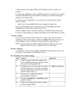
Page 45: ...he terminal emulation Type CR and the or OK prompt will appear 4 Accessing the CTP depends on your prompt If you see type ctp CR If you see OK type atds0 CR The CTP banner appears as shown in Figure 3 1 If no prompt appears verify that these steps have been followed correctly 5 Enter your password and type CR The Main menu appears as shown in Figure 3 2 Note The default password is blank If a pass...

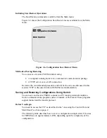
Page 46: ...e 3 2 shows the Control Port Main menu Figure 3 2 Control Port Main Menu The Enter Selection prompt appearing at the bottom of the screen accepts a number corresponding to the choices in the particular menu For example to logout from the CTP back to the or OK prompt you would enter 1 CR ...

Page 47: ...ntrol O Enable the display of reports to the Control Port N Control N Disable the display of reports to the Control Port or HELP Get help at any level of input To get a brief description of a parameter while configuring a record i e a port record type CR after the prompt for the parameter in question see Figure 3 3 Figure 3 3 Example of Online Help The help information gives you The range of accep...

Page 48: ...le 6 2 3 is equivalent to typing 6 CR then 2 CR and then 3 CR but you will get new menu screens after each CR CR steps you through the different parameters Also you must enter CR for the changes to take effect This performs an initialization function known as a boot See Booting the Node on page 7 for more information Figure 3 4 Example Port Configuration Accessing Frame Relay Station Configuration...

Page 49: ... for the node to initialize 2 Enable the Default Node switch 3 Press the reset button and allow the Vanguard 100 PC to reboot Wait 1 minute for the node to initialize 4 Disable the Default Node switch The Node default is complete Examining Statistics From the Main menu type 5 CR to display the different choices for statistics You can view various node port station and connection details from withi...

Page 50: ...nstallation diskette This diskette contains a readme txt file that will assist you with installing a version of Software Loader that runs under Windows Note You will only need to install a different software image if you need an application other that what is supported in the Toronto image Before You Begin You must have a copy of the Vanguard CD ROM or images provided from your local service repre...

Page 51: ... does not contain PPP the next choice for a defaulted node on Port 3 will be the SLIP protocol then the ATPAD protocol and finally the PAD protocol If your software image does not contain FRI the default choice for Port 1 and Port 2 will be the X 25 protocol Saving and Restoring Configurations The Vanguard 100 PC allows you to save and restore a node s configuration memory CMEM Saving a configurat...

Page 52: ...ill be the only one discussed in this section TFTP is discussed in the full 6500 Series documentation Saving and Restoring Configurations Using Kermit You can save and restore CMEM contents to a PC running terminal emulation from a communications program suchas Crosstalk or ProComm These programs support the Kermit file transfer protocol Before You Begin You need to access the CTP as described in ...

Page 53: ...to restore a configuration with a communications package Step Action Result 1 Access the Control Port From the Main menu type 15 1 CR Characters such as N3 appear at the prompt You receive the following message Receive complete File stored successfully If Then The transfer failed because too much time elapsed Try again 2 Depending on the communications program installed the steps for using Kermit ...

Page 54: ...ration Note If you would like to submit to Motorola a preconfigured CMEM that you believe would benefit other users of this product Motorola would be happy to receive it Please use the following as a guideline for the information youprovide Overview of Supplied CMEMs The CMEMs that have beenprovided are all fully described in this chapter These descriptions are in the following format Configuratio...

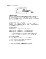
Page 55: ...tions Port 2 PPP RFC1490 encapsulation 57600 bps VJ compression Port 3 PPP RFC1490 encapsulation 57600 bps VJ compression FRI Port 1 Station 1 connects to PPP Port 3 FRI 1s1 PPP 3 FRI Port 1 Station 2 connects to PPP Port 2 FRI 2s2 PPP 2 CTP access via CTP switch Optional Application CMEMs V1000001 MEM Standard application as mentioned in Summary V1000001 001 Port 2 PAD CTP access via PAD or switc...

Page 56: ...ions Port 2 SLIP RFC1490 encapsulation 57600 Auto detect comp Port 3 SLIP RFC1490 encapsulation 57600 Auto detect comp FRI Port 1 Station 1 connects to SLIP Port 3 FRI 1s1 SLIP 3 FRI Port 1 Station 2 connects to SLIP Port 2 FRI 1s2 SLIP 2 CTP access via CTP switch Optional Application CMEMs V1000002 MEM Standard application as mentioned in Summary V1000002 001 Port 2 PAD CTP access via PAD or swit...

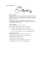
Page 57: ... PPP port number i e 757503 is valid for connection to PPP 3 999902 is valid for PPP 2 Configuration Summary Port 1 FRI Annex D ext clk 1 Auto learn DLCI Annex G Port 2 PPP RFC1490 encapsulation 57600 bps VJ compression Port 3 PPP RFC1490 encapsulation 57600 bps VJ compression Connections achieved by the Network Service calling the PPP port CTP access via CTP switch or X 25 service calling subaddr...

Page 58: ...to the SLIP port number i e 757503 is valid for connection to SLIP 3 999902 is valid for SLIP 2 Configuration Summary Port 1 FRI Annex D ext clk 1 Auto learn DLCI Annex G Port 2 SLIP RFC1490 encapsulation 57600 Auto detect comp Port 3 SLIP RFC1490 encapsulation 57600 Auto detect comp Connections achieved by the Network Service calling the SLIP port CTP access via CTP switch or X 25 service calling...

Page 59: ...to SLIP 3 999902 is valid for SLIP 2 Configuration Summary Port 1 X 25 RFC877 ext clk 16 svc s DTE Port 2 PPP RFC1490 encapsulation 57600 VJ Compression Port 3 PPP RFC1490 encapsulation 57600 VJ Compression Connections achieved by the X 25 Service calling the PPP port CTP access via CTP switch or X 25 service calling subaddress 98 Optional Application CMEMs V1000005 MEM Standard application as men...

Page 60: ...ection to SLIP 3 999902 is valid for SLIP 2 Configuration Summary Port 1 X 25 RFC877 ext clk 16 svc s DTE Port 2 SLIP RFC1490 encapsulation 57600 Auto detect comp Port 3 SLIP RFC1490 encapsulation 57600 Auto detect comp Connections achieved by the X 25 Service calling the SLIP port CTP access via CTP switch or X 25 service calling subaddress 98 Optional Application CMEMs V1000006 MEM Standard appl...

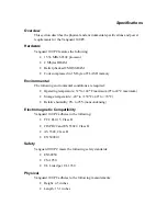
Page 61: ...environmental conditions are required Operating temperature 32 to 104 F maximum 0 to 40 C maximum Storage temperature 40 to 158 F 40 to 70 C Relative humidity 0 to 95 noncondensing Electromagnetic Compatibility Vanguard 100 PC adheres to the following FCC Part 15 Class B CISPR 22 and EN 55022 Class B AS 3548 Class B EN 50082 1 Safety Vanguard 100 PC meets the following safety standards EN60950 CSA...

Page 62: ... 37 1 6 V 36 DIM 130 23 21 1 2 V 11 DIM 80 0 1 0 5 DSU Daughtercard 80 0 0 0 4 ISDN U Daughtercard 320 0 0 1 6 ISDN S T Daughtercard 13 0 0 0 1 To determine the total power requirements of your configuration add the columns for the components installed on your board Weight Vanguard 100 PC weighs the following Vanguard 100 PC card with DIM 0 57 lb 0 26 kg DSU daughtercard 0 21 lb 0 1 kg V 24 daught...

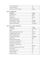
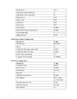
Page 63: ...FRI Bypass Station PPP Port SLIP Port PAD Port SNMP Agent X25 Port Configuration Parameter Value Connection Type SIMP Port Control NONE Clock Source EXT Clock Speed 56000 Link Address DTE Number of PVC Channels 0 Starting PVC Channel Number 1 Number of SVC Channels 16 Starting SVC Channel Number 1 Initial Frame SABM T1 Transmission Retry Timer 1 10 sec 30 T4 Poll Timer 40 N2 Transmission Tries 10 ...

Page 64: ... of Routing Digits in Call User Data 5 Number of Routing Digits in Call User Data 5 Number of prefix Address Digits stripped from Outgoing Calls 0 Number of prefix Address Digits stripped from Incoming Calls 0 Restricted Connection Destination blank Port Address blank CUG Membership Billing Records OFF Number of Subaddress Digits in X 25 Address 2 Idle Disconnect Timer sec 0 Call Security DISABLE ...

Page 65: ...upport ANNEX_D FRI Annex_G Station Configuration Parameter Value Station Type ANNEX_G DLCI 0 Committed Information Rate CIR 16000 Committed Burst Size BC 16000 End to End Transit Delay 50 Congestion Control Mode NORMAL Link Address DTE Number of PVC Channels 0 Starting PVC Channel Number 1 Number of SVC Channels 16 Starting SVC Channel Number 1 Initial Frame SABM T1 Transmission Retry Timer 1 10 s...

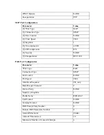
Page 66: ...FRI Bypass Station Configuration Parameter Value Station Type BYPASS DLCI 0 Committed Information Rate CIR 16000 Committed Burst Size BC 16000 End to End Transit Delay 50 Congestion Control Mode NORMAL PPP Port Configuration Parameter Value Connection Type SIMP Flow Control NONE Clock Speed 115200 Stop Bits 1 Authentication Protocol NONE LCP Options PFC ACFC ACCM MRU Maximum Receive Unit 1500 Netw...

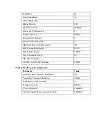
Page 67: ... 3 Encapsulation RFC1490 PAD Port Configuration Parameter Value Port Type PAD Connection Type SIMP Port Control NONE Port Speed 9600 Auto Baud Sequence CR_only Data Bits per Character 8 Device Parity NONE Number of Stop Bits 1 Profile Name DEFAULT Call Control NONE Terminal Control NONE PAD Prompt Entry Number 0 Remote PAD Parameters Number 0 Autocall Mnemonic blank Autocall Timeout sec 10 Maximum...

Page 68: ...m Receive Buffer Length 128 PAD Command Language CCITT NUI Facility Format ODPN NUI Verification Timer 60 Max NUI Violations 3 Action Type for NUI Violations NONE Typical SNMP Agent Configuration Parameter Value SNMP UDP Connection Subaddress 161 Secondary Channel Subaddress blank UDP Retry Timer seconds 10 Connection Type SIP_W Trap Generation DISABLE Authentication Failure Trap Generation DISABL...

Reviews: