background image

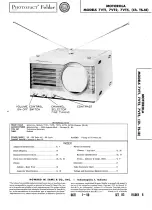
Summary of Contents for 7VT1 Series

Page 1: ...urements 11 18 12 17 4 9 2 5 o o m Ul S n oo HOWARD W SAMS CO INC Indianapolis 1 Indiana The listing of any available replacement part herein does not consfitute in any case a recommendation warranty or guaranty by Howard W Sams Co Inc as to the quality and suitability of such replacement part The numbers of these parts have been compiled from information furnished to Howard W Sams Co Inc by the m...

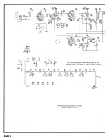
Page 2: ...MIXER AJ12AT7 1000 r MMF 7 Y A PHOTOFACT STANDARD NOTATION SCHEMATIC Howard W Sams Co Inc 1950 PAGE 2 ...

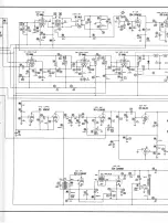
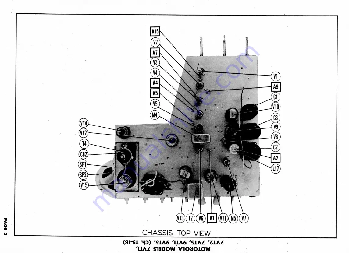
Page 3: ...SOUND IF AMP AUDIO OUTPUT 25L6G 3 ...

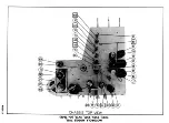
Page 4: ...MOTOROLA MODELS 7VH 7VT2 7VT5 9VT1 9VT5 Ch TS 18 ...

Page 5: ...MOTOROLA MODELS 7VT1 7VT2 7VT5 9VT1 9VT5 Ch TS 18 M3IA dOl SISSVHD ...

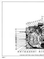
Page 6: ...CHASSIS BOTTOM VIEW TRANS INDUCT PAGE 4 ...

Page 7: ...UCTOR AND ALIGNMENT IDENTIFICATION PAGE 9 ...

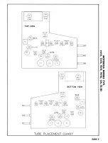
Page 8: ...F CONVERTER 6AU6 6AU6 6AU6y l2AT7y 6AG5y 3RD VIDEO IE 1ST VIDEO IF REAMP L 17 V9 8 25L6OT z ID1O OUTPUT BOTTOM VIEW 2ND VIDEO IF I2AT7 6AU6 AU6 6AU6 RF AMR 1ST VIDEO IF 3RD VIDEO IFI T2 I V I I C I2SN7GT CLIPPER TUBE PLACEMENT CHART PAGE 5 ...

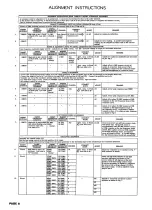
Page 9: ...h side to ungrounded tube shield floating over converter tube V2 Low side to B SWEEP GENERATOR FREQUENCY 24 6MC 12MC Sweep ii L SWEEP GENERATOR FREQUENCY 24 6MC 12MC Sweep MARKER GENERATOR FREQUENCY 22 9MC 26 SMC t IF TRANSF MARKER GENERATOR FREQUENCY 23 IMC 26 IMC CHANNEL Any ORMER AL CHANNEL Any CONNECT SCOPE Vert Amp to Point Low side to B 11 GNMENT CONNECT SCOPE Low side to B ADJUST A4 AS A6 A...

Page 10: ...SMC 61 25MC 65 75MC 55 25MC 59 75MC CHANNEL 10 7 8 9 11 12 13 6 5 4 3 2 CONNECT SCOPE Vert Amp to Point Low side to B ADJUST A15 A16 A17 A18 A19 A20 A21 A22 A23 A24 A25 REMARKS Adjust to place 195MC marker at peak of response curve as per Fig 5 Check all high band channels for response curve similar to Fig 5 Note the possible variation If necessary slightly expand or compress L4 to obtain proper r...

Page 11: ... 6ATI6 6AU6 6AU6 6AL5 12SN7GT 25L6GT 12SN7GT 6SL7GT 12SN7GT 25L6GT B3GT Pin 1 15KO iooon 1 5 Meg t2 Meg 41000 1 Mee a 6 8KO 4 7 Mee Inf IMej 10 Meg 18 Kn 8 5KSJ Inf Tnf PINS 1 2 V16 7JP4 On t750Kn fSOOKJJ Tin 2 680 33KSJ 82n 820 1S2O 1 5Kn 150n 6 8KO t440Kn 320 1 Meg 20 Meg t20Kn t520n 23 50 50 Mee Pin 3 280 1 2KJJ 23n 19n 13 80 a en 292 4 20 on 22on On on 2oon t32oo Inf Pin 4 260 230 19 sn 14 an ...

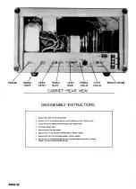
Page 12: ...ws holding rear cover Remove cover 3 Loosen twoscrews holding antenna terminal lugs Remove lugs 4 Disconnectspeaker plug 5 Remove picture tube base socket 6 Remove four 1 4 hex bead bolts holding chassis Remove chassis 7 Remove four 5 16 hex nuts holding speaker Remove speaker 8 Remove one 1 4 hex head bolt and two 11 32 hex nuts holding picture tube mounting bracket Remove mounting bracket and tu...

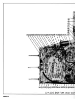
Page 13: ...CHASSIS BOTTOM VIEW CAP PAGE 18 ...

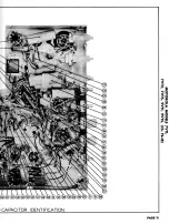
Page 14: ... CAPACITOR IDENTIFICATION PAGE 11 ...

Page 15: ...LJ cr i Ld O DQ CO CO CO I 0 ...

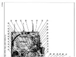
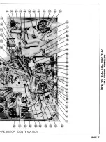
Page 16: ... RESISTOR IDENTIFICATION PAGE 17 ...

Page 17: ...MOTOROLA MODELS 7VT1 7VT2 7VT5 9VT1 9VT5 Ch TS 18 vocna ...

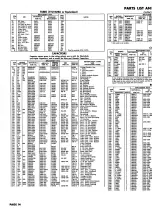
Page 18: ...GP2L 001 GP2L 001 811 005 811 005 GP2K 250 811 005 GP2L 001 GP2K 750 GP2K 250 811 005 811 005 GP2K 500 GP2L 001 821 01 811 005 GP2L 001 GP2 335 01 GP2 335 01 GP2K 250 GP2L 001 GP1K 100 GP2K 250 GP2K 250 GPLK 100 SPRAGUE PART No D6282 TVL 46 TVL 5I TVA 14 TVA 21 MS 31 1FM 31 1FM 31 1FM 21 1FM 21 1FM 21 36C1 29C1 29C1 MS 415 1FM 21 1FM 325 1FM 32S 1FM 21 TC 2 29C1 TC 5 29C1 1FM 325 29C1 1FM 21 1FM 2...

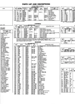
Page 19: ...d be removed from new control to allow tongue of insulated shaft to engaged into slot 5 Saw shaft of new control to desired length and file slot in shaft to duplicate original use original insulated spacer bushing and shaft with new control RESISTORS ITEM No Tl T2 T3A B RATING DC RESISTANCE PRI 590 59 1 270n 2100 SEC 170 1 170O MOTC PAR 24B48I 24B48I 25B901 ITEM No Rll R12 R13 R14 R1S R16 H17 R18 ...

Page 20: ...ode Video IF Decoupling Video IF Coil Shunt ige Dropping Video IF Cathode Video IF Decoupling Network o Amp Grid ige Divider o Amp Plate o Amp Decoupling ige Divider d IF Cathode d IF Decoupling ncing mphasis Det Diode Load Det Diode Load irid late late Decoupling at Grid nt Cathode tion Clipper Grid Clipper Plate Clipper Grid Clipper Plate rator rator back Osc Grid Osc Plate ge Divider Amp Grid A...

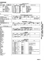
Page 21: ...90427 36K790426 36K791439 36K791442 36K791437 61C790434 NOTES Channel selector Includes fine tuning trimmer and coils assy Less tuning core 8MMF 500V 1000MMF 500V 15MMF 500V Video Detector Panel 8 2KJJ 330SJ 1N34 Brass Lll L13 M4A Iron and Screw L16 L9 Primary Iron and Screw L9 Secondary Iron and Screw L17 Primary Iron and Screw L17 Secondary Antenna Includes line cord assy Model 7VT1 Includes lin...

Reviews: