background image

Profile Configuration


7-39

7. Select 

OK

 to save the changes made within the Certificate Revocation screen. Select 

Reset

 to revert to 

the last saved configuration.

7.4.3 Setting the Profile’s NAT Configuration

Profile Security Configuration

Network Address Translation 

(NAT) is a technique to modify network address information within IP packet 

headers in transit across a traffic routing device. This enables mapping one IP address to another to protect 
network address credentials. With typical deployments, NAT is used as an IP masquerading technique to 
hide private IP addresses behind a single, public facing, IP address. 

NAT is a process of modifying network address information in IP packet headers while in transit across a 
traffic routing device for the purpose of remapping one IP address to another. In most deployments NAT is 
used in conjunction with IP masquerading which hides RFC1918 private IP addresses behind a single public 
IP address.

NAT can provide a profile outbound Internet access to wired and wireless hosts connected to an AP-6511. 
Many-to-one NAT is the most common NAT technique for outbound Internet access. Many-to-one NAT 
allows an Access Point to translate one or more internal private IP addresses to a single, public facing, IP 
address assigned to a 10/100/1000 Ethernet port or 3G card.

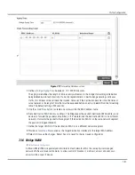
To define a NAT configuration that can be applied to a profile:

1. Select the Configuration tab from the Web UI

2. Select 

Profiles

 from the Configuration tab.

3. Either select 

Add

 if creating a new profile or 

Edit

 if modifying the configuration on an existing profile.

4. Select 

Security

.

5. Select 

NAT

.

Summary of Contents for AP-6511

Page 1: ...Motorola Solutions AP 6511 Access Point System Reference Guide ...

Page 2: ...Motorola Solutions AP 6511 Access Point System Reference Guide 1 2 ...

Page 3: ...2 5 Configurable Objects 2 6 2 2 6 Configuration Objects 2 9 2 2 7 Configuration Operation Icons 2 9 2 2 8 Access Type Icons 2 10 2 2 9 Administrative Role Icons 2 10 2 2 10 Device Icons 2 11 Chapter 3 Getting Started 3 1 Using the Initial Setup Wizard 3 2 Chapter 4 Dashboard 4 1 Dashboard 4 2 4 1 1 Dashboard Conventions 4 2 4 1 1 1 Health 4 2 4 1 1 2 Inventory 4 6 4 2 Network View 4 9 4 2 1 Filte...

Page 4: ...y Configuration 5 63 5 4 3 1 Overriding a Profile s General Security Settings 5 64 5 4 3 2 Overriding a Profile s Certificate Revocation List CRL Configuration 5 66 5 4 3 3 Overriding a Profile s NAT Configuration 5 68 5 4 4 Overriding a Profile s Services Configuration 5 75 5 4 5 Overriding a Profile s Management Configuration 5 77 5 4 6 Overriding a Profile s Miscellaneous Configuration 5 81 Cha...

Page 5: ...orwarding Database 7 30 7 3 6 Bridge VLAN 7 31 7 3 7 Miscellaneous Network Configuration 7 33 7 3 8 Profile Network Configuration and Deployment Considerations 7 34 7 4 Profile Security Configuration 7 36 7 4 1 Defining Profile Security Settings 7 36 7 4 2 Setting the Certificate Revocation List CRL Configuration 7 38 7 4 3 Setting the Profile s NAT Configuration 7 39 7 4 4 Profile Security Config...

Page 6: ...Authentication Configuration 10 10 10 1 1 4 Setting the SNMP Configuration 10 11 10 1 1 5 SNMP Trap Configuration 10 14 10 1 2 Management Access Deployment Considerations 10 15 Chapter 11 Diagnostics 11 1 Fault Management 11 2 11 2 Snapshots 11 5 11 2 1 Core Snapshots 11 5 11 2 2 Panic Snapshots 11 6 11 3 Advanced Diagnostics 11 7 11 3 1 UI Debugging 11 7 Chapter 12 Operations 12 1 Device Operatio...

Page 7: ...de 13 27 13 3 5 AP Detection 13 28 13 3 6 Wireless Client 13 29 13 3 7 Wireless LANs 13 30 13 3 8 Radios 13 32 13 3 8 1 Radio Status 13 33 13 3 8 2 Radio RF Statistics 13 34 13 3 8 3 Radio Traffic Statistics 13 35 13 3 9 Interfaces 13 36 13 3 9 1 General Statistics 13 37 13 3 9 2 Viewing Interface Statistics Graph 13 41 13 3 10 Network 13 41 13 3 10 1 ARP Entries 13 42 13 3 10 2 Route Entries 13 4...

Page 8: ...3 13 2 RSA Keys 13 57 13 3 14 WIPS 13 58 13 3 14 1 WIPS Events 13 59 13 3 15 Captive Portal 13 59 13 3 16 Network Time 13 60 13 3 16 1 NTP Status 13 61 13 3 16 2 NTP Association 13 62 13 4 Wireless Client Statistics 13 64 13 4 1 Health 13 64 13 4 2 Details 13 67 13 4 3 Traffic 13 70 ...

Page 9: ...information for specific user needs Installation Guide Describes the basic hardware setup and configuration required to transition to a more advanced configuration of the AP Motorola Solutions AP 6511 Access Point System Reference Guide this guide Describes configuration of the Motorola Solutions AP 6511 Access Point using the Access Point s resident Web UI NOTE The screens and windows pictured in...

Page 10: ...sed to highlight the following Screen names Menu items Button names on a screen Bullets indicate Action items Lists of alternatives Lists of required steps that are not necessarily sequential Sequential lists e g those that describe step by step procedures appear as numbered lists NOTE Indicate tips or special requirements CAUTION Indicates conditions that can cause equipment damage or data loss W...

Page 11: ... 5 supported AP 6511 Access Point see Web UI Overview on page 2 1 The WiNG 5 architecture is a solution designed for 802 11n networking It leverages the best aspects of independent and dependent architectures to create a smart network that meets the connectivity quality and security needs of each user and their applications based on the availability of network resources including wired networks By...

Page 12: ... bottleneck is avoided and the destination is reached without latency or performance degradation This behavior delivers a significantly better quality of experience for the end user The same distributed intelligence enables more resilience and survivability since the Access Points keep users connected and traffic flowing with full QoS security and mobility even if the connection to the wireless co...

Page 13: ... to function as either a Controller AP Standalone AP or Dependent mode AP In Controller AP mode an AP 6511 can manage up to 25 other AP 6511s and share data amongst managed Access Points In Standalone mode an AP 6511 functions as an autonomous non controller adopted Access Point servicing wireless clients In Dependent mode an AP 6511 is reliant on its connected controller for its dependent mode co...

Page 14: ...d with the Web UI Firefox 3 6 Internet Explorer 7 x Internet Explorer 8 x 2 1 2 Connecting to the Web UI 1 Connect one end of an Ethernet cable to any of the LAN ports on the AP 6511 and connect the other end to a computer with a working Web browser 2 Set the computer to use an IP address between 192 168 0 10 and 192 168 0 250 on the connected port Set a subnet network mask of 255 255 255 0 3 Once...

Page 15: ...d the management interface 7 If this is the first time the management interface has been accessed a dialogue displays to start the initial setup wizard For more information on using the initial setup wizard see Using the Initial Setup Wizard on page 3 2 ...

Page 16: ... This section lists global icons available throughout the interface Logoff Select this icon to log out of the system This icon is always available and is located at the top right hand corner of the UI Add Select this icon to add a row in a table When this icon is selected a new row is created in the table or a dialog box opens where you can enter values for that particular list Delete Select this ...

Page 17: ...he policy and select this button Entry Updated Indicates a value has been modified from its last saved configuration Entry Update States that an override has been applied to a device s profile configuration Mandatory Field Indicates the control s value is a mandatory configuration item You will not be allowed to proceed further without providing all mandatory values in this dialog Error in Entry I...

Page 18: ...ss from completing Intervention might still be required to resolve subsequent warnings Success Indicates everything is well within the network or a process has completed successfully without error Information This icon always precedes information displayed to the user This may either be a message displaying progress for a particular process or may just be a message from the system Device Configura...

Page 19: ...ration has been impacted A bridging policy defines which VLANs are bridged and how local VLANs are bridged between the wired and wireless sides of the network RF Domain States an RF Domain configuration has been impacted RF Domain implement location based security restrictions applicable to all VLANs in a particular physical location Firewall Policy Indicates a Firewall policy has been impacted Fi...

Page 20: ...ith captive portal to provide hotspot services to wireless clients DHCP Server Policy Indicates a DHCP server policy is being applied DHCP provides IP addresses to wireless clients A DHCP server policy configures how DHCP provides these IP addresses RADIUS Group Indicates the configuration of RADIUS Group is being defined and applied A RADIUS group is a collection of RADIUS users with the same set...

Page 21: ...s the status of all the processes and memory when a process fails Panic Snapshots Indicates a panic snapshot has been generated A panic snapshot is a file that records the status of all the processes and memory when a failure occurs UI Debugging Select this icon link to view current NETCONF messages View UI Logs Select this icon link to view the different logs generated by the user interface FLEX ...

Page 22: ...le access permission A user with this permission is permitted to access an associated device using the device s serial console Superuser Indicates superuser privileges A superuser has complete access to all configuration aspects of the device to which the user is connected System States system user privileges A system user is allowed to configure some general settings like boot parameters licenses...

Page 23: ... retrieve logs and reboot the AP 6511 Web User Indicates a Web user privilege A Web user is allowed accessing the device s Web user interface System This icon indicates system wide impact Cluster This icon indicates a cluster A cluster is a set of AP 6511s that work collectively to provide redundancy and load sharing Access Point This icon indicates any access point that is a part of the network W...

Page 24: ...Motorola Solutions AP 6511 Access Point System Reference Guide 2 12 ...

Page 25: ...process of accessing the wireless network for the first time The wizard helps configure location network and WLAN settings and aids in the discovery of access points For instructions on how to use the initial setup wizard as well as an example walkthrough see Using the Initial Setup Wizard on page 3 2 ...

Page 26: ...s method the last two bytes of the AP 6511 MAC address become the last two octets of the IP address AP 6511 MAC address 00 C0 23 00 F0 0A AP 6511 IP address equivalent 169 254 240 10 To derive the AP 6511 s IP address using its factory assigned MAC address a Open the Windows calculator be selecting Start All Programs Accessories Calculator This menu path may vary slightly depending on your version...

Page 27: ...ect this option when deploying the AP 6511 as a Controller AP managed access point Selecting this option closes the Initial Setup Wizard A Dependant AP obtains its configuration from a profile stored on the Controller AP Any manual configuration changes on a Dependant AP are overwritten by the Controller AP upon reboot A Dependent AP requires a Controller AP in the network For this example choose ...

Page 28: ...tion and Contact name Select a Time Zone and Country for the AP 6511 Changing the default password is critical before any configuration refinements are made to protect the data exchanged between the AP 6511 and its peers Ensure the Location represents the AP 6511 s deployment area and the Contact accurately reflects the administrator responsible for this AP 6511 ...

Page 29: ...3 4 Initial Setup Wizard System Information 9 Select any or all of access methods HTTP HTTPS Telnet or SSHv2 used for connecting to this AP 6511 access point 10 Select the Next button to continue to the Topology Selection screen ...

Page 30: ...are available in subsequent screens For the purposes of this example select Router Mode 12 Click the Next button to continue to the LAN Configuration screen Router Mode In Router Mode the AP 6511 routes the traffic between the local network LAN and internet or external network WAN Bridge Mode Displays the device s factory assigned MAC address used as hardware identifier The MAC address cannot be r...

Page 31: ...P Address Subnet Enter an IP Address and a subnet for the LAN interface If the Use DHCP checkbox is selected this field is not configurable Use DHCP To enable automatic network configuration using a DHCP Server select the Use DHCP checkbox If this option is enabled the LAN IP Address Subnet DHCP Address Assignment and Domain Name fields are populated by the DHCP server What VLAN ID should be used ...

Page 32: ...anced VLAN Configuration button to set associations between VLANs and physical interfaces Use the Controller to assign IP addresses to devices Select the Use the Controller to assign IP addresses to devices checkbox to enable the DHCP server to provide IP and DNS information to clients on the LAN interface IP Address Range Enter a starting and ending IP Address range to assign to clients on the LA...

Page 33: ...and a subnet for the controller s WAN interface If the Use DHCP checkbox is enabled this field is not configurable Use DHCP To enable automatic network configuration using a DHCP Server select the Use DHCP checkbox If this option is enabled the WAN IP Address Subnet and Gateway fields are populated by the DHCP server What VLAN ID should be used for the WLAN interface Use the spinner to select the ...

Page 34: ...ally enabled on the AP 6511 17 To add a WLAN select Add WLAN What port is connected to the external network Use the drop down menu to select the physical port connected to the WAN interface Enable NAT on the WAN Interface Click the Enable NAT on WAN Interface checkbox to enable Network Address Translation NAT allowing traffic to pass between the WAN and LAN interfaces Default Gateway Enter an IP A...

Page 35: ... changed by the user The maximum number of characters available for the SSID is 32 Do not use any of the following characters SSID WLAN Type Use the WLAN Type to select a basic authentication and encryption scheme for a AP 6511 WLAN Available options include No authentication no encryption Captive portal authentication no encryption PSK authentication WPA2 encryption EAP authentication WPA2 encryp...

Page 36: ...ction is required within this screen Select Next Commit to continue to the AP Discovery screen VLAN Id Use the drop down menu to select a VLAN to segregate traffic for this WLAN All configured VLANs are available for selection WPA Key Enter either an alphanumeric string of 8 to 63 ASCII characters or 64 HEX characters as the primary string both transmitting and receiving authenticators must share ...

Page 37: ...nts discovered by the AP 6511 The screen lists their Model Hostname MAC Address and Serial Number If you have connected any APs recently select the Refresh List button to update the list of known APs Optionally define a Hostname for each known AP 21 Click the Next button to continue on the Wireless Client Association screen ...

Page 38: ... Association screen displays adopted wireless clients and the WLANs they are associated with To verify the WLAN configuration associate a wireless client with each configured AP 6511 WLAN After associating click the Refresh button to update the list of associated wireless clients Select Save Next when completed to continue to the Date and Time screen ...

Page 39: ...on 24 Select Finish to complete the AP 6511 Initial Setup Wizard Once complete a configuration profile is created and assigned to the AP 6511 In addition to the Diagram and Event Log tabs available thus far a Complete tab displays confirming the completion of the Initial Setup Wizard The Complete tab lists the changes made to the user interface to configure the AP 6511 The Complete tab lists the u...

Page 40: ...olutions AP 6511 Access Point System Reference Guide 3 16 Figure 3 14 Initial Setup Wizard Completed 25 Once you have reviewed the changes click the Close button to exit the wizard and return the AP 6511 s Web UI ...

Page 41: ...ed network Use the dashboard to review the current network topology assess the network s component health and diagnose problematic device behavior By default the Dashboard screen displays the System Dashboard screen which is the top level in the device hierarchy The dashboard provides the following tools and diagnostics Dashboard Network View ...

Page 42: ...elect Dashboard Dashboard The Dashboard displays the Health tab by default Figure 4 1 Dashboard screen Health tab 4 1 1 Dashboard Conventions The Dashboard displays AP 6511 information using the following conventions Health Displays information about the state of the AP 6511 managed network Inventory Displays information on the physical devices being managed by the AP 6511 4 1 1 1 Health Health Th...

Page 43: ...reen Health tab Information in this tab is classified as Device Details Radio RF Quality Index Radio Utilization Index Client RF Quality Index 4 1 1 1 1 Device Details Health The Device Details field displays model and version information ...

Page 44: ... It s a percentage of the overall effectiveness of the RF environment It s a function of the data rate in both directions the retry rate and the error rate Figure 4 4 Radio RF Quality Index RF Quality displays as the average quality index for the single RF Domain utilized by the AP 6511 The table lists the bottom five 5 RF quality values for the AP 6511 s RF Domain The quality is measured as 0 20 ...

Page 45: ...ization is defined as the percentage of throughput relative to the maximum possible throughput for the AP 6511 s RF Domain Refer to the number or errors and dropped packets to assess AP 6511 radio performance relative to the number of packets both transmitted and received Periodically select Refresh at the bottom of the screen to update the radio utilization information displayed Figure 4 5 Radio ...

Page 46: ...of managed devices The screen contains links to display more granular data specific to a specific radio Figure 4 7 System screen Inventory tab Information is partitioned into the following fields Radio Types WLAN Utilization Wireless Clients Client on Channels Worst 5 Lists to worst 5 performing client radios connected to this AP 6511 Client MAC Displays the factory encoded MAC address assigned to...

Page 47: ...of this AP 6511 Periodically select Refresh at the bottom of the screen to update the radio information 4 1 1 2 6 WLAN Utilization Inventory The WLAN Utilization field displays the top 5 WLANs utilized by this AP 6511 in respect to deployment on behalf of AP 6511 client support Figure 4 9 Device Types field The table displays how effectively each WLAN is utilized its WLAN name and each listed WLAN...

Page 48: ...rmation to assess if an AP 6511 managed radio is optimally deployed in respect to its radio type and intended client support requirements 4 1 1 2 8 Client on Channels Inventory The Client of Channels field displays a bar graph for wireless clients segregated by their operating frequency Information for each channel is further classified based on 802 11x band Figure 4 11 Client On Channel field For...

Page 49: ...shboard Overview Network Figure 4 12 Network View Topology The screen displays icons for the different views that can be created Apart from device specific icons the following three icons are available default Displays information about the AP 6511 s default RF Domain system Displays information about the current system Use these icons to navigate within the Network view and manipulate the display...

Page 50: ...y contains an expandable System column where peer AP 6511 Access Points can be selected and expanded to displays connected peers Use the System area as required to review device connections within an AP 6511 managed network Many of these peer devices are available for device connection to Controller AP mode AP 6511s Figure 4 14 Network View System field 4 2 1 Filters Field Network View The Filters...

Page 51: ... in the range of 60 100 percent SNR Select this option to filter based on a signal to noise ratio in decibels The available filter ranges are Poor 0 14 Filters clients based on the SNR value in the range of 0 14 Average 15 24 Filters clients based on the SNR value in the range of 15 24 Good 25 100 Filters clients based on the SNR value in the range of 25 100 Threat Select this option to filter bas...

Page 52: ...oded MAC address and serial number While this information cannot be modified by the administrator it does enable the administrator to review the device s system uptime within the AP 6511 managed network Figure 4 16 AP 6511 Device Specific Information Optionally select the Statistics link at the bottom of the display a screen where Access Point device data can be reviewed on a much more granular le...

Page 53: ...istered design For more information see RF Domain Overrides on page 5 24 Profiles enable administrators to assign a common set of configuration parameters and policies to Access Points Profiles can be used to assign shared or unique network wireless and security parameters to Access Points across a large multi segment site The configuration parameters within a profile are based on the hardware mod...

Page 54: ... devices collectively without having to modify individual device configurations To assign a device am AP 6511 a Basic Configuration 1 Select the Configuration tab from the Web UI 2 Select Devices from the Configuration tab 3 Select a target device by double clicking it from amongst those displayed within the Device Configuration screen Devices can also be selected directly from the Device Browser ...

Page 55: ...in or Profile the device supports Building Assign the target a device a Building name representative of the location the device is physically deployed The name cannot exceed 64 characters Assigning a building name is helpful when grouping devices in Profiles as devices in the same physical deployment location may need to share specific configuration parameters in respect to radio transmission and ...

Page 56: ... is unavailable Select Refresh as required to update the device s system time Use the New Time parameter to set the calendar day hour and minute Use the AM and PM radio buttons to refine whether the updated time is for the AM or PM When completed select Update Clock to commit the updated time to the AP 6511 7 Select OK to save the changes to the basic configuration Selecting Reset reverts the scre...

Page 57: ...h certificate is digitally signed by a trustpoint The trustpoint signing the certificate can be a certificate authority corporation or individual A trustpoint represents a CA identity pair containing the identity of the CA CA specific configuration parameters and an association with an enrolled identity certificate SSH keys are a pair of cryptographic keys used to authenticate users instead of or ...

Page 58: ...mote location for archive and retrieval as required for application to other devices To configure trustpoints for use with certificates 1 Select Launch Manager from either the HTTPS Trustpoint SSH RSA Key or RADIUS Server Certificate parameters HTTPS Trustpoint Either use the default trustpoint or select the Stored radio button to enable a drop down menu where an existing certificate trustpoint ca...

Page 59: ...efault 2 Select a device from amongst those displayed to review its certificate information Refer to the Certificate Details to review the certificate s properties self signed credentials validity period and CA information 3 To optionally import a certificate select the Import button from the Certificate Management screen The Import New Trustpoint screen displays ...

Page 60: ...e actual characters used in the key Leaving the Show checkbox unselected displays the passphrase as a series of asterisks URL Provide the complete URL to the location of the trustpoint If needed select Advanced to expand the dialog to display network address information to the location of the target trustpoint The number of additional fields that populate the screen is also dependent on the select...

Page 61: ...d for cf usb1 and usb2 Path Specify the path to the trustpoint Enter the complete relative path to the file on the server Trustpoint Name Enter the 32 character maximum name assigned to the target trustpoint signing the certificate A trustpoint represents a CA identity pair containing the identity of the CA CA specific configuration parameters and an association with an enrolled identity certifica...

Page 62: ...ed The most common reason for revocation is the user no longer being in sole possession of the private key For information on creating the CRL used with a trustpoint refer to Setting the Certificate Revocation List CRL Configuration on page 7 38 Protocol Select the protocol used for importing the target CA certificate Available options include tftp ftp sftp http cf usb1 usb2 Port Use the spinner c...

Page 63: ...arget CRL The number of additional fields that populate the screen is dependent on the selected protocol Cut and Paste Select the Cut and Paste radio button to copy an existing CRL into the cut and past field When pasting a CRL no additional network address information is required URL Provide the complete URL to the location of the CRL If needed select Advanced to expand the dialog to display netw...

Page 64: ...ch prevents its further use Figure 5 7 Certificate Management Import Signed Cert screen 13 Define the following configuration parameters required for the Import of the CA certificate IP Address Enter IP address of the server used to import the CRL This option is not valid for cf usb1 and usb2 Hostname Provide the hostname of the server used to import the CRL This option is not valid for cf usb1 an...

Page 65: ...ey If there s more than one RADIUS authentication server export the certificate and don t generate a second key unless you want to deploy two root certificates URL Provide the complete URL to the location of the signed certificate If needed select Advanced to expand the dialog to display network address information to the location of the signed certificate The number of additional fields that popu...

Page 66: ... actual characters used in the key Leaving the Show checkbox unselected displays the passphrase as a series of asterisks URL Provide the complete URL to the location of the trustpoint If needed select Advanced to expand the dialog to display network address information to the location of the target trustpoint The number of additional fields that populate the screen is also dependent on the selecte...

Page 67: ...ificate request generate a new key or import or export an existing key to and from a remote location Rivest Shamir and Adleman RSA is an algorithm for public key cryptography It s an algorithm that can be used for certificate signing and encryption When a device trustpoint is created the RSA key is the private key used with the trustpoint To review existing device RSA key configurations generate a...

Page 68: ...rent RSA key configuration Each key can have its size and character syntax displayed Once reviewed optionally generate a new RSA key import a key from a selected device export a key to a remote location or delete a key from a selected device 4 Select Generate Key to create a new key with a defined size Figure 5 10 Certificate Management Generate RSA Key screen ...

Page 69: ... of the key between 1 024 2 048 bits Motorola Solutions recommends leaving this value at the default setting of 1024 to ensure optimum functionality Key Name Enter the 32 character maximum name assigned to the RSA key Key Passphrase Define the key used by both the AP 6511 and the server or repository of the target RSA key Select the Show textbox to expose the actual characters used in the passphra...

Page 70: ...erate a second key unless you want to deploy two root certificates Figure 5 12 Certificate Management Export RSA Key screen Protocol Select the protocol used for importing the target key Available options include tftp ftp sftp http cf usb1 usb2 Port Use the spinner control to set the port This option is not valid for cf usb1 and usb2 IP Address Enter IP address of the server used to import the RSA...

Page 71: ...lf signed certificate Key Name Enter the 32 character maximum name assigned to the RSA key Key Passphrase Define the key passphrase used by both the AP 6511 and the server Select the Show textbox to expose the actual characters used in the passphrase Leaving the Show checkbox unselected displays the passphrase as a series of asterisks URL Provide the complete URL to the location of the key If need...

Page 72: ...ociatedwith the certificate Atrustpoint represents a CA identity pair containing the identity of the CA CA specific configuration parameters and an association with an enrolled identity certificate Use an Existing RSA Key Select the radio button and use the drop down menu to select the existing key used by both the device and the server or repository of the target RSA key Create a New RSA Key To c...

Page 73: ... button to automatically create the certificate s subject credentials or select user defined to manually enter the credentials of the self signed certificate The default setting is auto generate Country C Define the Country of deployment for the certificate The field can be modified by the user to other values This is a required field and must not exceed 2 characters State ST Enter a State Prov fo...

Page 74: ...te Management screen Figure 5 14 Certificate Management Create CSR screen 3 Define the following configuration parameters required to Create New Certificate Signing Request CSR Use an Existing RSA Key Select the radio button and use the drop down menu to select the existing key used by both the device and the server or repository of the target RSA key Create a New RSA Key To create a new RSA key s...

Page 75: ... the CSR This is a required field City L Enter a City to represent the city name used in the CSR This is a required field Organization O Define an Organization for the organization used in the CSR This is a required field Organizational Unit OU Enter an Org Unit for the name of the organization unit used in the CSR This is a required field Common Name CN If there s a common name IP address for the...

Page 76: ...port roles are quite similar However device configurations may need periodic refinement from their original RF Domain administered design Unlike a RFS series controller an AP 6511 Access Point supports a single RF domain To define a device s RF Domain override configuration 1 Select the Configuration tab from the Web UI 2 Select Devices from the Configuration tab 3 Select a target device by double...

Page 77: ... power to compensate for the coverage loss NOTE A blue override icon to the left of any parameter defines the parameter as having an override applied To revert the override back to its original setting select the override icon to display an Action pop up Select the Remove Override checkbox to revert the override to its original setting Location Displays the location set for the device as part of i...

Page 78: ...e mitigation techniques to block the devices by manual termination air lockdown or port suppression 10 Select the Create icon to define a new WIPS policy that can be applied to the RF Domain or select the Edit icon to modify or override an existing WIPS policy For an overview of WIPS and instructions on how to create a WIPS policy that can be used with a RF Domain see Intrusion Prevention on page ...

Page 79: ...m a profile configuration shared amongst numerous devices deployed within a particular site Use Profile Overrides to define configurations overriding the parameters set by the target device s original profile assignment To review a profile s original configuration requirements and the options available for a target device refer to Profile Configuration on page 7 1 To define a general profile overr...

Page 80: ...terface configuration can have overrides applied to customize the configuration to a unique deployment However once an override is applied to this configuration it becomes independent from the profile that may be shared by a group of devices in a specific deployment and my need careful administration until a profile can be re applied to the target device For more information refer to the following...

Page 81: ...target device by double clinking it from amongst those displayed within the Device Configuration screen Devices can also be selected directly from the Device Browser in the lower left hand side of the UI 4 Select Profile Overrides from the Device menu to expand it into sub menu options 5 Select Interface to expand its sub menu options 6 Select Ethernet Ports Figure 5 17 Profile Overrides Ethernet ...

Page 82: ...the port untagged with no 802 1Q header All frames received on the port are expected as untagged and mapped to the native VLAN If set to Trunk the port allows packets from a list of VLANs added to the trunk A port configured as Trunk supports multiple 802 1Q tagged VLANs and one Native VLAN which can be tagged or untagged Native VLAN Lists the numerical VLAN ID 1 4094 set for the native VLAN The n...

Page 83: ...o enable the port to automatically exchange information about data transmission speed and duplex capabilities Auto negotiation is helpful when in an environment where different devices are connected and disconnected on a regular basis Automatic is the default setting Duplex Select either half full or automatic as the duplex option Select Half duplex to send data over the port then immediately rece...

Page 84: ... tagged or untagged Access is the default mode Native VLAN Use the spinner control to define a numerical Native VLAN ID between 1 4094 The native VLAN allows an Ethernet device to associate untagged frames to a VLAN when no 802 1Q frame is included in the frame Additionally the native VLAN is the VLAN which untagged traffic will be directed over when using a port in trunk mode The default VLAN is ...

Page 85: ... Firewall on page 8 2 16 Refer to the Trust field to define the following Trust ARP Responses Select the radio button to enable ARP trust on this port ARP packets received on this port are considered trusted and information from these packets is used to identify rogue devices within the network The default value is disabled Trust DHCP Responses Select the radio button to enable DHCP trust on this ...

Page 86: ...sers on this port 18 Select OK to save the changes made to the Ethernet port s security configuration Select Reset to revert to the last saved configuration if you do not wish to commit the overrides NOTE Some vendor solutions with VRRP enabled send ARP packets with Ethernet SMAC as a physical MAC and inner ARP SMAC as VRRP MAC If this configuration is enabled a packet is allowed despite a conflic...

Page 87: ... an existing configuration 1 Select the Configuration tab from the Web UI 2 Select Devices from the Configuration tab 3 Select a target device by double clinking it from amongst those displayed within the Device Configuration screen Devices can also be selected directly from the Device Browser in the lower left hand side of the UI 4 Select Profile Overrides from the Device menu to expand it into s...

Page 88: ...eated or an existing one modified 9 If creating a new Virtual Interface use the Name spinner control to define a numeric ID between 1 4094 Name Displays the name of each listed Virtual Interface assigned when it was created The name is between 1 4094 and cannot be modified as part of a Virtual Interface edit Type Displays the type of Virtual Interface for each listed interface Description Displays...

Page 89: ... address in order to reach the LAN over the switch managed network None No NAT activity takes place This is the default setting 16 Select OK button to save the changes and overrides to the Basic Configuration screen Select Reset to revert to the last saved configuration Description Provide or edit a description up to 64 characters for the Virtual Interface that helps differentiate it from others w...

Page 90: ...ts and packet traffic to and from connected clients If a firewall rule does not exist suiting the data protection needs of this Virtual Interface select the Create icon to define a new firewall rule configuration or the Edit icon to modify or override an existing configuration For more information see Wireless Firewall on page 8 2 19 Select the OK button located at the bottom right of the screen t...

Page 91: ...within the Device Configuration screen Devices can also be selected directly from the Device Browser in the lower left hand side of the UI 3 Select Profile Overrides from the Device menu to expand it into sub menu options 4 Select Interface to expand its sub menu options 5 Select Radios Figure 5 23 Profile Overrides Access Point Radios screen NOTE A blue override icon to the left of a parameter de...

Page 92: ...ts supported profile A red X defines the Virtual Interface as currently disabled The interface status can be modified when a new Virtual Interface is created or an existing one modified RF Mode Displays whether each listed radio is operating in the 802 11a n or 802 11b g n radio band If the radio is a dedicated sensor it will be listed as a sensor to define the radio as not providing typical WLAN ...

Page 93: ...tended operation select the Create icon to define a new QoS policy that can be applied to this profile For more information see Radio QoS Policy on page 6 48 Association ACL Use the drop down menu to specify an existing Association ACL policy to apply to the Access Point radio An Association ACL is a policy based Access Control List ACL that either prevents or allows wireless clients from connecti...

Page 94: ...rt function A setting of 0 defines the radio as using Smart RF to determine its output power 20 dBm is the default value Antenna Gain Set the antenna between 0 00 30 00 dBm The access point s Power Management Antenna Configuration File PMACF automatically configures the access point s radio transmit power based on the antenna type its antenna gain provided here and the deployed country s regulator...

Page 95: ...in requirements for radio emissions The default setting is Indoors Max Clients Use the spinner control to set the maximum permissible client connections for this radio set a value between 1 128 Beacon Interval Set the interval between radio beacons in milliseconds either 50 100 or 200 A beacon is a packet broadcast by adopted radios to keep the network synchronized Included in a beacon is informat...

Page 96: ...eshold A higher RTS threshold minimizes RTS CTS exchanges consuming less bandwidth for data transmissions A disadvantage is less help to nodes that encounter interference and collisions An advantage is faster data frame throughput Environments with less wireless traffic and contention for transmission make the best use of a higher RTS threshold Short Preamble If using an 802 11bg radio select this...

Page 97: ...nt Administrators can assign each WLAN its own BSSID If using a single radio access point there are 8 BSSIDs available If using a dual radio access point there are 8 BSSIDs for the 802 11b g n radio and 8 BSSIDs for the 802 11a n radio 13 Select OK to save the changes and overrides to the WLAN Mapping Select Reset to revert to the last saved configuration 14 Select the Advanced Settings tab ...

Page 98: ... Receive Consider setting this value to None for high priority traffic to reduce packet delay A MPDU Modes Use the drop down menu to define the A MPDU mode supported Options include Transmit Only Receive Only Transmit and Receive and None The default value is Transmit and Receive Using the default value long frames can be both sent and received up to 64 KB When enabled define either a transmit or ...

Page 99: ...TIM or only follow DTIM when using Power Save Aware mode The default setting is Follow DTIM Client Count Weight Sets the client load per Access Point radio between 0 10 Motorola Solutions recommends considering the client load on an Access Point before defining its radio configuration The higher the number of clients the greater the strain on a radio s resources The default weight is 10 clients Se...

Page 100: ...names into IP addresses If one DNS server doesn t know how to translate a particular domain name it asks another one until the correct IP address is returned DNS enables access to resources using human friendly notations DNS converts human friendly domain names into notations used by different networking equipment for locating resources As a resource is accessed using human friendly hostnames it s...

Page 101: ...ied To revert the override back to its original profile setting select the override icon to display an Action pop up Select the Remove Override checkbox to revert the override to its original setting for this profile Enable Domain Lookup Select the radio button to enable DNS When enabled human friendly domain names can be converted into numerical IP destination addresses The radio button is select...

Page 102: ...broadcasts a request packet in a special format to all the machines on the LAN to see if one machine knows it has that IP address associated with it A machine that recognizes the IP address as its own returns a reply indicating as such ARP updates the ARP cache for future reference and then sends the packet to the MAC address that replied To define an ARP supported configuration 1 Select Devices f...

Page 103: ...et to revert to the last saved configuration VLAN Use the spinner control to select a VLAN for an address requiring resolution IP Address Define the IP address used to fetch a MAC Address MAC Address Displays the target MAC address that s subject to resolution This is the MAC used for mapping an IP address to a MAC address that s recognized on the network Device Type Specify the device type the AR...

Page 104: ...to a packet This QoS assignment can be overridden as needed but removes the device configuration from the managed profile that may be shared with other similar device models To define an QoS configuration for DSCP mappings 1 Select Devices from the Configuration tab 2 Select a target device by double clicking it from amongst those displayed within the Device Configuration screen Devices can also b...

Page 105: ...anges and overrides Select Reset to revert to the last saved configuration DSCP Lists the DSCP value as a 6 bit parameter in the header of every IP packet used for packet classification 802 1p Priority Assign a 802 1p priority as a 3 bit IP precedence value in the Type of Service field of the IP header used to set the priority The valid values for this field are 0 7 Up to 64 entries are permitted ...

Page 106: ...ct Devices from the Configuration tab 2 Select a target device by double clicking it from amongst those displayed within the Device Configuration screen Devices can also be selected directly from the Device Browser in the lower left hand side of the UI 3 Select Profile Overrides from the Device menu to expand it into sub menu options 4 Select Network to expand its sub menu options 5 Select Static ...

Page 107: ... not match any other routes in the routing table A gateway routes traffic from a managed device to another network segment The default gateway connects the network to the outside network Internet The gateway is associated with a router which uses headers and forwarding tables to determine where packets are sent providing the path for the packet in and out of the gateway Setting a default gateway f...

Page 108: ...his forwarding database assignment can be overridden as needed but removes the device configuration from the managed profile that may be shared with other similar device models To define or override a profile s forwarding database configuration 1 Select Devices from the Configuration tab 2 Select a target device by double clicking it from amongst those displayed within the Device Configuration scr...

Page 109: ...orwarding table The default setting is 300 seconds 7 Use the Add Row button to create a new row within the MAC address table 8 Set or override a destination MAC Address address The bridge reads the packet s destination MAC address and decides to forward the packet or drop filter it If it s determined the destination MAC is on a different network it forwards the packet to the segment If the destina...

Page 110: ... destined to some other device which will untag it When a data frame is received on a port the VLAN bridge determines the associated VLAN based on the port of reception Using forwarding database information the Bridge VLAN forwards the data frame on the appropriate port s VLAN s are useful to set separate networks to isolate some computers from others without actually having to have separate cabli...

Page 111: ...he description should be unique to the VLAN s specific configuration and help differentiate it from other VLANs with similar configurations Edge VLAN Mode Defines whether the VLAN is currently in edge VLAN mode An edge VLAN is the VLAN where hosts are connected For example if VLAN 10 is defined with wireless clients and VLAN 20 is where the default gateway resides VLAN 10 should be marked as an ed...

Page 112: ...ts are used to update the IP MAC Table to prevent IP spoof and arp cache poisoning attacks Trust DHCP Responses When DHCP trust is enabled a green checkmark displays When disabled a red X displays When enabled DHCP packets from a DHCP server are considered trusted and permissible within the network DHCP packets are used to update the DHCP Snoop Table to prevent IP spoof attacks Description If crea...

Page 113: ... Responses Select the radio button to use DHCP packets from a DHCP server as trusted and permissible within the network DHCP packets are used to update the DHCP Snoop Table to prevent IP spoof attacks This feature is disabled by default Overlaid VLAN Select this checkbox to separate this VLAN from the wired VLAN used by the AP 6511 This feature is disabled by default ...

Page 114: ...mongst those displayed within the Device Configuration screen Devices can also be selected directly from the Device Browser in the lower left hand side of the UI 3 Select Profile Overrides from the Device menu to expand it into sub menu options 4 Select Network to expand its sub menu options 5 Select Miscellaneous Figure 5 34 Profile Overrides Network Miscellaneous screen 6 Select the Include Host...

Page 115: ...I to the Configuration Security portion of the UI to create the required security policy configuration Once created a policy s configuration can have an override applied as needed to meet the changing data protection requirements of a device s deployed environment However in doing so this device must now be managed separately from the profile configuration shared by other device models within the ...

Page 116: ...efine a profile s security settings and overrides 1 Select Devices from the Configuration tab 2 Select a target device by double clicking it from amongst those displayed within the Device Configuration screen Devices can also be selected directly from the Device Browser in the lower left hand side of the UI 3 Select Profile Overrides from the Device menu to expand it into sub menu options 4 Select...

Page 117: ...work The means by which this is accomplished varies but in principle a firewall can be thought of as mechanisms both blocking and permitting data traffic within the network If an existing Firewall policy does not meet your requirements select the Create icon to create a new firewall policy that can be applied to this profile An existing policy can also be selected and overridden as needed using th...

Page 118: ...cking it from amongst those displayed within the Device Configuration screen Devices can also be selected directly from the Device Browser in the lower left hand side of the UI 3 Select Profile Overrides from the Device menu to expand it into sub menu options 4 Select Security to expand its sub menu options 5 Select Certificate Revocation Figure 5 36 Profile Overrides Certificate Revocation screen...

Page 119: ...ithin the Trustpoint Name field The name cannot exceed 32 characters b Enter the resource ensuring the trustpoint s legitimacy within the URL field c Use the spinner control to specify an interval in hours after which a device copies a CRL file from an external server and associates it with a trustpoint 7 Select OK to save the changes and overrides made within the Certificate Revocation screen Sel...

Page 120: ...des outbound Internet access to wired and wireless hosts Many to one NAT is the most common NAT technique for outbound Internet access Many to one NAT allows the Access Point to translate one or more private IP addresses to a single public facing IP address assigned to a 10 100 1000 Ethernet port or 3G card To define a NAT configuration or override that can be applied to a profile 1 Select Devices...

Page 121: ...es created thus far Any of these policies can be selected and applied to a profile 6 Select Add to create a new NAT policy that can be applied to a profile Select Edit to modify or override the attributes of a existing policy or select Delete to remove obsolete NAT policies from the list of those available to a profile Figure 5 38 NAT Pool screen ...

Page 122: ...ic NAT screen Name If adding a new NAT policy provide a name to help distinguish it from others with similar configurations The length cannot exceed 64 characters Prefix Length Use the spinner control to set the netmask between 1 30 of the network the pool address belongs to IP Address Range Define a range of IP addresses hidden from the public Internet NAT modifies network address information in ...

Page 123: ...translation hides the actual address of the server from users on insecure interfaces Casual access by unauthorized users becomes much more difficult Static NAT requires a dedicated address on the outside network for each host Inside NAT is the default setting 10 Select the Destination tab to view destination NAT configurations and define packets passing through the NAT on the way back to the LAN a...

Page 124: ...l used by applications requiring guaranteed delivery It s a sliding window protocol handling both timeouts and retransmissions TCP establishes a full duplex virtual connection between two endpoints Each endpoint is defined by an IP address and a TCP port number The User Datagram Protocol UDP offers only a minimal transport service non guaranteed datagram delivery and provides applications direct a...

Page 125: ...requires packets be switched through a NAT router to generate translations in the translation table Figure 5 42 Profile Overrides Dynamic NAT screen NAT IP Enter the IP address of the matching packet to the specified value The IP address modified can be either source or destination based on the direction specified NAT Port Enter the port number of the matching packet to the specified value This op...

Page 126: ...ot exposed to the outside world when the translation address is used to interact with the remote destination Network Displays Inside or Outside NAT as the network direction for the dynamic NAT configuration Interface Lists the VLAN between 1 4094 used as the communication medium between the source and destination points within the NAT configuration Overload Type Select the radio button to define t...

Page 127: ...esses once translated will not be exposed to the outside world when the translation address is used to interact with the remote destination Network Select Inside or Outside NAT as the network direction for the dynamic NAT configuration Inside is the default setting Interface Use the drop down menu to select the VLAN between 1 4094 used as the communication medium between the source and destination...

Page 128: ...ofile For more information see Configuring a Captive Portal Policy on page 9 2 6 Use the DHCP Server Policy drop down menu assign this profile a DHCP server policy If an existing DHCP policy does not meet the profile s requirements select the Create icon to create a new policy configuration that can be applied to this profile or the Edit icon to modify the parameters of an existing DHCP Server pol...

Page 129: ...onfiguration if deployment requirements change and a devices configuration must be modified from its original device profile configuration Additionally an administrator can define a profile with unique configuration file and device firmware upgrade support To define or override a profile s management configuration 1 Select Devices from the Configuration tab 2 Select a target device by double click...

Page 130: ...licies are usable Use the drop down menu to select an existing management policy to apply to this profile If no management policies exist meeting the data access requirements of this profile select the Create icon to access a series of screens used to define administration access control and SNMP configurations Select an existing policy and select the Edit icon to modify the configuration of an ex...

Page 131: ...s can be sent on behalf of the profile Select Clear as needed to remove an IP address Facility to Send Log Messages Use the drop down menu to specify the local server facility if used for the profile event log transfer Syslog Logging Level Event severity coincides with the syslog logging level defined for the profile Assign a numeric identifier to log events based on criticality Severity levels in...

Page 132: ...upgrade from a local file 13 Select OK to save the changes and overrides made to the profile s Management Firmware configuration Select Reset to revert to the last saved configuration Enable Firmware Upgrade Select this option to enable automatic firmware upgrades for this profile from a user defined remote location This value is disabled by default Enable Controller Upgrade of AP Firmware Select ...

Page 133: ...e last saved configuration 5 4 6 Overriding a Profile s Miscellaneous Configuration Refer to the advanced profile s Miscellaneous menu item to set or override a profile s NAS configuration The profile database on the RADIUS server consists of user profiles for each connected network access server NAS port Each profile is matched to a username representing a physical port When users are authorized ...

Page 134: ...re a RADIUS message originates 3 Set a NAS Port Id Attribute up to 253 characters in length This is the RADIUS NAS port ID attribute which identifies the device port where a RADIUS message originates 4 Refer to the Turn off LEDs option to disable an adopted Access Point s LEDs This feature is enabled by default 5 Select OK to save the changes made to the profile s Advanced Miscellaneous configurat...

Page 135: ...h as guest access control and asset tracking Each WLAN configuration contains encryption authentication and QoS policies and conditions for user connections Connected access point radios transmit periodic beacons for each BSS A beacon advertises the SSID security requirements supported data rates of the wireless network to enable clients to locate and connect to the WLAN WLANs are mapped to radios...

Page 136: ...Motorola Solutions AP 6511 Access Point System Reference Guide 6 2 Figure 6 1 Configuration Wireless field ...

Page 137: ...its SSID and client management properties modified SSID Displays the name of the SSID assigned to the WLAN when it was created or last modified Optionally select a WLAN and click the Edit button to update the SSID Description Displays the brief description defined for each listed WLAN when it was either created or modified WLAN Status Lists each WLANs current status as either Active or Shutdown A ...

Page 138: ...owever typical deployments only map a single VLAN to a WLAN The use of a pool is strictly optional Authentication Type Displays the name of the authentication scheme this WLAN is using to secure its client membership transmissions None is listed if authentication is not used within this WLAN Refer to the Encryption type column if no authentication is used to verify there is some sort of data prote...

Page 139: ...SID Enter or modify the Services Set Identification SSID associated with the WLAN The WLAN name is auto generated using the SSID until changed by the user The maximum number of characters that can be used for the SSID is 32 Description Provide a textual description for the WLAN to help differentiate it from others with similar configurations A description can be up to 64 characters in length WLAN ...

Page 140: ...tive Motorola Solutions recommends one VLAN be deployed for secure WLANs while separate VLANs be defined for each WLAN providing guest access 6 1 2 Configuring WLAN Security Wireless LAN Policy A WLAN can be assigned a security policy supporting authentication captive portal hotspot or encryption schemes QoS Policy Use the drop down menu to assign an existing QoS policy to the WLAN or select the C...

Page 141: ...cation PSK None Secure guest access to the network is referred to as captive portal A captive portal is guest access policy for providing guests temporary and restrictive access to the wireless network The primary means of securing such guest access is the use of a hotspot Existing captive portal policies can be applied to a WLAN to provide secure guest access A captive portal policy s hotspot con...

Page 142: ... can be deployed with WEP WPA or WPA2 encryption schemes to further protect user information forwarded over wireless controller managed WLANs The EAP process begins when an unauthenticated supplicant client device tries to connect with an authenticator in this case the authentication server An Access Point passes EAP packets from the client to an authentication server on the wired side of the acce...

Page 143: ...orted by the WLAN 7 Select OK when completed to update the WLAN s EAP configuration Select Reset to revert the screen back to the last saved configuration EAP EAP PSK and EAP MAC Deployment Considerations 802 1x EAP EAP PSK and EAP MAC Before defining a 802 1x EAP EAP PSK or EAP MAC supported configuration on a WLAN refer to the following deployment guidelines to ensure the configuration is optima...

Page 144: ...new AAA policies can be created A default AAA policy is also available if configuring a WLAN for the first time and there s no existing policies Select the Edit icon to modify the configuration of a selected AAA policy Authentication authorization and accounting AAA is a framework for intelligently controlling access to the wireless client managed network enforcing user authorization policies and ...

Page 145: ...cated guess access is required with the selected WLAN This feature is disabled by default 8 Select the Captive Portal Policy to use with the WLAN from the drop down menu If no relevant policies exist select the Create icon to define a new policy to use with this WLAN or the Edit icon to update the configuration of an existing Captive Portal policy For more information see Configuring Captive Porta...

Page 146: ... a WLAN 1 Select Configuration Wireless Wireless LAN Policy to display a high level display of the existing WLANs available to the wireless network 2 Select the Add button to create an additional WLAN or select an existing WLAN and select Edit to modify the properties of an existing WLAN 3 Select Security 4 Select the WPA WPA2 TKIP radio button from within the Select Encryption field The screen po...

Page 147: ...itting and receiving authenticators must share The alphanumeric string allows character spaces The wireless controller converts the string to a numeric value This passphrase saves the administrator from entering the 256 bit key each time keys are generated Unicast Rotation Interval Define an interval for unicast key transmission in seconds 30 86 400 Some clients have issues using unicast key rotat...

Page 148: ...duces a totally different result WPA2 CCMP is based on the concept of a Robust Security Network RSN which defines a hierarchy of keys with a limited lifetime similar to TKIP Like TKIP the keys the administrator provides are used to derive other keys Messages are encrypted using a 128 bit secret key and a 128 bit block of data The end result is an encryption scheme as secure as any for associated c...

Page 149: ...red to define a WPA2 CCMP configuration for the new or existing WLAN Figure 6 6 WPA2 CCMP screen 5 Define Key Settings 6 Define Key Rotation values Pre Shared Key Enter either an alphanumeric string of 8 to 63 ASCII characters or 64 HEX characters as the primary string both transmitting and receiving authenticators must share The alphanumeric string allows character spaces The wireless controller ...

Page 150: ...ncrypting decrypting broadcast traffic will be alternatively rotated based on the defined interval Define an interval for broadcast key transmission in seconds 30 86 400 Key rotation enhances the broadcast traffic security on the WLAN This value is disabled by default Pre Authentication Selecting the Pre Authentication option enables an associated client to carry out an 802 1x authentication with ...

Page 151: ...and 802 1 X EAP authentications WEP is optimal for WLANs supporting legacy deployments when also used with 802 1X EAP authentication to provide user and device authentication and dynamic WEP key derivation and periodic key rotation 802 1X provides authentication for devices and also reduces the risk of a single WEP key being deciphered WEP 64 uses a 40 bit key concatenated with a 24 bit initializa...

Page 152: ...ther proprietary routers and Motorola clients use the algorithm to convert an ASCII string to the same hexadecimal number Clients without Motorola adapters need to use WEP keys manually configured as hexadecimal numbers Keys 1 4 Use the Key 1 4 fields to specify key numbers For WEP 64 40 bit key the keys are 10 hexadecimal characters in length Select one of these keys for default activation by cli...

Page 153: ...ides authentication for devices and also reduces the risk of a single WEP key being deciphered If 802 1X support is not available on the legacy device MAC authentication should be enabled to provide device level authentication WEP 128 uses a 104 bit key which is concatenated with a 24 bit initialization vector IV to form the RC4 traffic key WEP may be all a small business user needs for the simple...

Page 154: ...character Pass Key and click the Generate button The pass key can be any alphanumeric string The wireless controller other proprietary routers and Motorola clients use the algorithm to convert an ASCII string to the same hexadecimal number Clients without Motorola adapters need to use WEP keys manually configured as hexadecimal numbers Keys 1 4 Use the Key 1 4 areas to specify key numbers For WEP ...

Page 155: ... see Wireless Firewall on page 8 2 WLANs use Firewalls like Access Control Lists ACLs to filter mark packets based on the WLAN from which they arrive as opposed to filtering packets on Layer 2 ports An ACL contains an ordered list of Access Control Entries ACEs Each ACE specifies an action and a set of conditions rules a packet must satisfy to match the ACE The order of conditions in the list is c...

Page 156: ...lect an existing inbound and outbound IP Firewall Rule using the drop down menu If no rules exist select the Create icon to display a screen where Firewall rules can be created Select the Edit icon to modify the configuration of a selected Firewall policy configuration If creating a new rule providing a name up to 64 characters long 4 Select the Add Row button 5 Select the added row to expand it i...

Page 157: ...proceed to its destination Source Enter both Source and Destination IP addresses The device uses the source IP address destination IP address and IP protocol type as basic matching criteria The access policy filter can also include other parameters specific to a protocol type like source and destination port for TCP UDP protocol Provide a subnet mask if needed Protocol Select the protocol used wit...

Page 158: ...ollowing actions are supported Log Creates a log entry that a Firewall rule has allowed a packet to either be denied or permitted Mark Modifies certain fields inside the packet and then permits them Therefore mark is an action with an implicit permit Mark Log Conducts both mark and log functions Precedence Use the spinner control to specify a precedence for this IP policy between 1 1500 Rules with...

Page 159: ... Log Conducts both mark and log functions Precedence Use the spinner control to specify a precedence for this MAC Firewall rule between 1 1500 Access policies with lower precedence are always applied first to packets VLAN ID Enter a VLAN ID representative of the shared SSID each user employs to interoperate within the network once authenticated by the local RADIUS server The VLAN ID can be between...

Page 160: ...ngs include wireless client inactivity timeouts and broadcast configurations 1 Select Configuration Wireless Wireless LAN Policy to display a high level display of the existing WLANs available to the wireless network 2 Select the Add button to create an additional WLAN or select and existing WLAN and Edit to modify the properties of an existing WLAN 3 Select the Client Settings tab Wireless Client...

Page 161: ...ireless clients for transmission The default value is 20 dBm Wireless Client Idle Time Set the maximum amount of time wireless clients are allowed to be idle within this WLAN Set the idle time in either Seconds 60 86 400 Minutes 1 1 440 Hours 0 24 or Days 0 1 When this setting is exceeded the client is no longer able to access resources and must re authenticate The default value is 1 800 seconds M...

Page 162: ... services by users This information is of great assistance in partitioning local versus remote users and how to best accommodate each Remote user information can be archived to a location outside of the switch for periodic network and user permission administration To configure WLAN accounting settings 1 Select Configuration Wireless LANs Wireless LAN Policy to display a high level display of the ...

Page 163: ...loyment guidelines to ensure the configuration is optimally effective When using RADIUS authentication Motorola Solutions recommends the WAN port round trip delay not exceed 150ms Excessive delay over a WAN can cause authentication and roaming issues When excessive delays exists a distributed RADIUS service should be used Motorola Solutions recommends authorization policies be implemented when use...

Page 164: ...ting wireless controller WLAN 3 Select Advanced Figure 6 14 WLAN Policy Advanced screen 4 Refer to the Protected Management Frames field to set a frame protection mode and security association for the WLAN s advanced configuration During a security association SA negotiation the wireless controller and recipient gateways agree to use a particular transform set to protect data flow A transform set ...

Page 165: ... relating to this WLAN Configuring a value here is optional and defaults are used if this is not configured per WLAN NAS Port The profile database on the RADIUS server consists of user profiles for each connected network access server NAS port Each profile is matched to a username representing a physical port When the wireless controller authorizes users it queries the user profile database using ...

Page 166: ... and 802 11n rates supported by the 2 4 GHz band and 802 11a and 802 11n rates supported by the 5 0 GHz radio band These are the rates wireless client traffic is supported within this WLAN If supporting 802 11n select a Supported MCS index Set a MCS modulation and coding scheme in respect to the radio s channel width and guard interval A MCS defines based on RF channel conditions an optimal combin...

Page 167: ...e as long as they support basic MCS as well as non 11n basic rates The selected rates apply to associated client traffic within this WLAN only 7 Select OK when completed to update this WLAN s advanced settings Select Reset to revert the screen back to its last saved configuration ...

Page 168: ...a list of QoS policies available to WLANs Each QoS policy has its own radio button that can be selected to edit its properties If none of the exiting QoS policies supports an ideal QoS configuration for the intended data traffic of this WLAN select the Add button to create new policy Select the radio button of an existing WLAN and select Ok to map the QoS policy to the WLAN displayed in the banner...

Page 169: ...oritized as best effort traffic on the radio Low Optimized for background traffic Implies all traffic on this WLAN is low priority on the radio SVP Prioritization A green checkmark defines the policy as having Spectralink Voice Prioritization SVP enabled to allow the wireless controller to identify and prioritize traffic from Spectralink Polycomm phones using the SVP protocol Phones using regular ...

Page 170: ...ss category are categorized by default as having best effort priority Applications assign each data packet to a given access category packets are then added to one of four independent transmit queues one per access category voice video best effort or background in the client The client has a collision resolution mechanism to address collision among different queues which selects the frames with th...

Page 171: ...ss Configuration 6 37 2 Select the Add button to create a new QoS policy or Edit to modify the properties of an existing WLAN QoS policy The WMM tab displays by default Figure 6 18 WLAN QoS Policy WMM screen ...

Page 172: ... supported only on certain legacy Motorola VOIP phones This feature is enabled by default Enable SVP Prioritization Enabling Spectralink Voice Prioritization SVP allows the wireless controller to identify and prioritize traffic from Spectralink Polycomm phones This gives priority to voice with voice management packets supported only on certain legacy Motorola VOIP phones If the Wireless Client Cla...

Page 173: ...ack off mechanism Lower values are used for higher priority traffic like video The available range is from 0 15 The default value is 3 ECW Max The ECW Max is combined with the ECW Min to create the contention value in the form of a numerical range From this range a random number is selected for the back off mechanism Lower values are used for higher priority traffic like video The available range ...

Page 174: ...s are used for lower priority traffic like Normal The available range is from 0 15 The default value is 10 Transmit Ops Use the slider to set the maximum duration a device can transmit after obtaining a transmit opportunity For higher priority traffic categories this value should be set to a low number The default value is 25 AIFSN Set the current AIFSN between 2 15 The default value is 3 ECW Min ...

Page 175: ...ata transmitted from the Access Point upstream and data transmitted from a WLAN s wireless clients back to their associated Access Point radios downstream Before defining rate limit thresholds for WLAN upstream and downstream traffic Motorola Solutions recommends you define the normal number of ARP broadcast multicast and unknown unicast packets that typically transmit and receive from each suppor...

Page 176: ...wireless client destinations By trending the typical number of ARP broadcast multicast and unknown unicast packets over a period of time the average rate for each access category can be obtained Once a baseline is obtained administrators should then add a minimum of a 10 margin to allow for traffic bursts at the site The default burst size is 320 kbytes Background Traffic Set a percentage value fo...

Page 177: ...y the network administrator using a time trend analysis The default threshold is 0 Enable Select the Enable radio button to enable rate limiting for data transmitted from Access Point radios to associated wireless clients Enabling this option does not invoke rate limiting for data traffic in the upstream direction This feature is disabled by default Rate Define an upstream rate limit between 50 1 ...

Page 178: ...nce a general downstream rate is known by the network administrator using a time trend analysis The default threshold is 50 Best Effort Traffic Set a percentage value for best effort traffic in the downstream direction This is a percentage of the maximum burst size for normal traffic Best effort traffic exceeding the defined threshold is dropped and a log message is generated Best effort traffic c...

Page 179: ...s Traffic that exceeds the defined rate is dropped by the client and a log message is generated The default rate is 1 000 kbps Maximum Burst Size Set a maximum burst size between 2 1024 kbytes The smaller the burst the less likely the upstream packet transmission will result in congestion for the wireless client The default burst size is 64 kbytes Background Traffic Set a percentage value for back...

Page 180: ...that exceeds the defined rate is dropped and a log message is generated The default rate is 1 000 kbytes Maximum Burst Size Set a maximum burst size between 2 64 kbytes The smaller the burst the less likely the downstream packet transmission will result in congestion for the wireless client The default burst size is 6 kbytes Background Traffic Set a percentage value for background traffic in the d...

Page 181: ...s themselves independent from the wireless clients these access point radios support Enabling WMM support on a WLAN only advertises WMM capability to wireless clients The wireless clients must be also able to support WMM and use the parameters correctly while accessing the wireless network to truly benefit Rate limiting is disabled by default on all WLANs To enable rate limiting a threshold must b...

Page 182: ...as defined a time interval for each traffic class known as the Transmit Opportunity TXOP The TXOP prevents traffic of a higher priority from completely dominating the wireless medium thus ensuring lower priority traffic is still supported by connected radios IEEE 802 11e includes an advanced power saving technique called Unscheduled Automatic Power Save Delivery U APSD that provides a mechanism fo...

Page 183: ...ng using 802 1X hotspot authentication and devices using MAC authentication 6 3 1 Radio QoS Configuration and Deployment Considerations Radio QoS Policy Before defining a radio QoS policy refer to the following deployment guidelines to ensure the configuration is optimally effective To support QoS each multimedia application wireless client and WLAN is required to support WMM WMM enabled clients c...

Page 184: ...rofiles Authorization functions through the assembly of attribute sets describing what the user is authorized to perform These attributes are compared to information contained in a database for a given user and the result is returned to AAA to determine the user s actual capabilities and restrictions Remote RADIUS servers authorize users by associating attribute value AV pairs with the appropriate...

Page 185: ...tart Stop Sends a start accounting notice at the beginning of a process and a stop notice at the end of a process The start accounting record is sent in the background The requested process begins regardless of whether the start accounting notice is received by the accounting server Request Interval Lists each AAA policy s interval to send a RADIUS accounting request to the RADIUS server NAC Polic...

Page 186: ...WLANs from within a WLAN Policy s Advanced configuration screen For more information on applying an existing Association ACL to a WLAN see Configuring Advanced WLAN Settings on page 6 30 To define an Association ACL deployable with a WLAN 1 Select Configuration Wireless Association ACL to display existing Association ACLs The Association Access Control List ACL screen lists those Association ACL p...

Page 187: ...uration is optimally effective Association ACL If creating an new Association ACL provide a name specific to its function Avoid naming it after a WLAN it may support The name cannot exceed 32 characters Precedence The rules within a WLAN s ACL are applied to packets based on their precedence values Every rule has a unique sequential precedence value you define You cannot add two rules s with the s...

Page 188: ...requirements of the particular WLANs they may map to However be careful not to name ACLs after specific WLANs as individual ACL policies can be used by more than one WLAN You cannot apply more than one MAC based ACL to a Layer 2 interface If a MAC ACL is already configured on a Layer 2 interface and a new MAC ACL is applied to the interface the new ACL replaces the previously configured one ...

Page 189: ...ctions by monitoring the network in real time and provides automatic mitigation from potentially problematic events such as radio interference coverage holes and radio failures Smart RF employs self healing to enable a WLAN to better maintain wireless client performance and site coverage during dynamic RF environment changes which typically require manual reconfiguration to resolve To define a Sma...

Page 190: ...ally created The name cannot be modified as part of the edit process Smart RF Policy Enable Displays a green check mark if Smart RF has been enabled for the listed policy A red X designates the policy as being disabled Interference Recovery Displays a green check mark if interference recovery has been enabled for the listed policy A red X designates coverage hole recovery being disabled Coverage H...

Page 191: ...dio button to enable this Smart RF policy for immediate inclusion with a RF Domain Smart RF is disabled by default Auto Assign Sensor Select the radio button to enable an AP 651 to auto assign a sensor radio for neighbor activity monitoring within the AP 6511 Smart RF supported network Interference Recovery Select the radio button to enable Interference Recovery when radio interference is detected...

Page 192: ...io coverage hole is detected within the Smart RF supported radio coverage area When coverage hole is detected Smart RF first determines the power increase needed based on the signal to noise ratio for a client as seen by the Access Point radio If a client s signal to noise value is above the threshold the transmit power is increased until the signal to noise rate falls below the threshold Coverage...

Page 193: ... to select a 1 20 dBm minimum power level for Smart RF to assign to a radio in the 5 GHz band 1 dBm is the default setting 5 0 GHz Maximum Power Use the spinner control to select a 1 20 dBm maximum power level Smart RF can assign a radio in the 5 GHz band 17 dBm is the default setting 2 4 GHz Minimum Power Use the spinner control to select a 1 20 dBm minimum power level Smart RF can assign a radio...

Page 194: ...er 802 11a or 802 11b g depending on the radio selected can still be serviced without interruption using 20 MHz Select Automatic to enable automatic assignment of channels to working radios to avoid channel overlap and avoid interference from external RF sources 40MHz is the default setting 2 4 GHz Channels Use the Select drop down menu to select the 2 4 GHz channels used in Smart RF scans 2 4 GHz...

Page 195: ...ring neighbor recovery Set the time in either Seconds 0 86 400 Minutes 0 1 440 or Hours 0 24 or Days 0 1 The default setting is 3 660 seconds 5 0 GHz Neighbor Recovery Power Threshold Use the spinner control to set a value between 85 to 55 dBm the 5 0 GHz radio uses as a maximum power increase threshold if the radio is required to increase its output power to compensate for a failed device radio w...

Page 196: ... channel This feature is enabled by default Client Threshold Use the spinner to set a client threshold for the Smart RF policy between 1 255 If threshold number of clients are connected to a radio it does not change its channel even though it requires one based on the interference recovery determination made by the smart master The default setting is 50 5 0 GHz Channel Switch Delta Use the spinner...

Page 197: ...rder for coverage hole recovery to trigger The default setting is 1 SNR Threshold Use the spinner control to set a signal to noise threshold between 1 75 dB This is the signal to noise threshold for an associated client as seen by its associated AP radio When exceeded the radio increases its transmit power in order to increase coverage for the associated client The default value is 20 dB Coverage ...

Page 198: ...ctive The Smart RF calibration process impacts associated users and should not be run during business or production hours The calibration process should be performed during scheduled maintenance intervals or non business hours For Smart RF to provide effective recovery RF planning must be performed to ensure overlapping coverage exists at the deployment site Smart RF can only provide recovery when...

Page 199: ...can be tracked and as profile members Their customized configurations overwrite their profile configurations until the profile can be re applied to the device Each AP 6511 model Access Point is automatically assigned a default profile A default profile for each supported model is automatically added to a device s configuration file when the device is discovered Default profiles can also be manuall...

Page 200: ...he AP uses to select the optimum controller for adoption By default an adoption policy generally distributes AP adoption evenly Modify existing adoption policies or create a new one as needed to meet the adoption requirements of this particular profile Firewall Policy Displays the existing firewall policy if any assigned to each listed profile Firewall policies can be assigned when creating or edi...

Page 201: ... 3 General Profile Configuration Profile Interface Configuration Profile Network Configuration Profile Security Configuration Profile Services Configuration Profile Management Configuration Miscellaneous Profile Configuration ...

Page 202: ...d or network clock synchronization within the network NTP is a client server implementation The AP 6511 periodically synchronizes its clock with a master clock an NTP server For example the AP 6511 resets its clock to 07 04 59 upon reading a time of 07 04 59 from its designated NTP server Additionally if the profile is supporting an Access Point the profile s general configuration provides an opti...

Page 203: ...ompared to the default radio configurations in previous WiNG releases is default profiles are used as pointers of an AP s configuration not just templates from which the configuration is copied Therefore if a change is made in one of the parameters in a profile the change is reflected across all APs using that profile Each user defined profile requires a unique name User defined profiles can be au...

Page 204: ...the following Ethernet Port Configuration Virtual Interface Configuration Access Point Radio Configuration Additionally deployment considerations and guidelines for profile interface configurations are available for review prior to defining a configuration that could significantly impact the performance of the network For more information see Profile Interface Deployment Considerations on page 7 2...

Page 205: ...guration as required Mode Displays the profile s current switching mode as either Access or Trunk as defined within the Ethernet Port Basic Configuration screen If Access is selected the listed port accepts packets only from the native VLAN Frames are forwarded out the port untagged with no 802 1Q header All frames received on the port are expected as untagged and mapped to the native VLAN If set ...

Page 206: ...to the appropriate VLAN When a frame is received with no 802 1Q header the upstream device classifies the frame using the default or native VLAN assigned to the Trunk port A native VLAN allows an Ethernet device to associate untagged frames to a VLAN when no 802 1Q frame is included in the frame Allowed VLANs Displays the VLANs allowed to send packets over the listed port Allowed VLANs are only li...

Page 207: ...formance needs dictate Automatic is the default setting Cisco Discover Protocol Receive Select the radio button to allow the Cisco discovery protocol for receiving data on this port Cisco Discover Protocol Transmit Select the radio button to allow the Cisco discovery protocol for transmitting data on this port Link Layer Discovery Protocol Receive Select this option to snoop LLDP on this port The ...

Page 208: ...stream Ethernet device does not support IEEE 802 1Q tagging it does not interpret the tagged frames When VLAN tagging is required between devices both devices must support tagging and be configured to accept tagged VLANs When a frame is tagged the 12 bit frame VLAN ID is added to the 802 1Q header so upstream Ethernet devices know which VLAN ID the frame belongs to The device reads the 12 bit VLAN...

Page 209: ...ed to A Virtual Interface is created for the default VLAN VLAN 1 to enable remote administration A Virtual Interface is also used to map VLANs to IP address ranges This mapping determines the destination networks for routing To review existing Virtual Interface configurations and either create a new Virtual Interface configuration modify an existing configuration or delete an existing configuratio...

Page 210: ... was created The name is between 1 4094 and cannot be modified as part of a Virtual Interface edit Type Displays the type of Virtual Interface for each listed interface Description Displays the description defined for the Virtual Interface when it was either initially created or edited Admin Status A green checkmark defines the listed Virtual Interface configuration as active and enabled with its ...

Page 211: ...ters for the Virtual Interface that helps differentiate it from others with similar configurations Admin Status Either select the Disabled or Enabled radio button to define this interface s current status within the network When set to Enabled the Virtual Interface is operational and available The default value is disabled Enable Zero Configuration The AP 6511 can use Zero Config for IP assignment...

Page 212: ...ed by the public IP address Outside Packets passing through the NAT on the way back to the LAN are searched against to the records kept by the NAT engine There the destination IP address is changed back to the specific internal private class IP address in order to reach the LAN over the network None No NAT activity takes place This is the default setting 12 Select OK button to save the changes to ...

Page 213: ...tom right of the screen to save the changes to the Security screen Select Reset to revert to the last saved configuration 7 2 3 Access Point Radio Configuration Profile Interface Configuration An AP 6511 model Access Point can have its radio configurations modified by a connected controller once its radios have successfully associated to the network Take care not to modify an Access Point s config...

Page 214: ...ly disabled The interface status can be modified when a new Virtual Interface is created or an existing one modified RF Mode Displays whether each listed radio is operating in the 802 11a n or 802 11b g n radio band If the radio is a dedicated sensor it will be listed as a sensor to define the radio as not providing typical WLAN support The radio band is set from within the Radio Settings tab Chan...

Page 215: ...traffic If there s no existing suiting the radio s intended operation select the Create icon to define a new QoS policy that can be applied to this profile For more information see Radio QoS Policy on page 6 48 Association ACL Use the drop down menu to specify an existing Association ACL policy to apply to the Access Point radio An Association ACL is a policy based Access Control List ACL that eit...

Page 216: ...in respect to its intended client support function A setting of 0 defines the radio as using Smart RF to determine its output power 20 dBm is the default value Antenna Gain Set the antenna between 0 00 30 00 dBm The access point s Power Management Antenna Configuration File PMACF automatically configures the access point s radio transmit power based on the antenna type its antenna gain provided he...

Page 217: ...x Clients Use the spinner control to set a maximum permissible number of clients to connect with this AP 6511 radio The available range is between 1 128 Beacon Interval Set the interval between radio beacons in milliseconds either 50 100 or 200 A beacon is a packet broadcast by adopted radios to keep the network synchronized Included in a beacon is information such as the WLAN service area the rad...

Page 218: ... lower RTS threshold A higher RTS threshold minimizes RTS CTS exchanges consuming less bandwidth for data transmissions A disadvantage is less help to nodes that encounter interference and collisions An advantage is faster data frame throughput Environments with less wireless traffic and contention for transmission make the best use of a higher RTS threshold Short Preamble If using an 802 11bg rad...

Page 219: ...ssign each WLAN its own BSSID If using a single radio access point there are 8 BSSIDs available If using a dual radio access point there are 8 BSSIDs for the 802 11b g n radio and 8 BSSIDs for the 802 11a n radio 11 Select the OK button located at the bottom right of the screen to save the changes to the WLAN Mapping Select Reset to revert to the last saved configuration 12 Select the Advanced Set...

Page 220: ...rted Options include Transmit Only Receive Only Transmit and Receive and None The default value is Transmit and Receive Using the default value long frames can be both sent and received up to 64 KB When enabled define either a transmit or receive limit or both Minimum Gap Between Frames Use the drop down menu to define the minimum gap between A MPDU frames in microseconds The default value is 4 mi...

Page 221: ...TIM when using Power Save Aware mode The default setting is Follow DTIM Client Count Weight Sets the client load per Access Point radio between 0 10 Motorola Solutions recommends considering the client load on an Access Point before defining its radio configuration The higher the number of clients the greater the strain on a radio s resources The default weight is 10 clients Setting the weight to ...

Page 222: ...hese configuration are optimally effective When changing from a default DHCP address to a fixed IP address set a static route first This is critical when the AP 6511 is being accessed from a subnet not directly connected to the Access Point and the default route was set from DHCP Take care not to modify an Access Point s configuration using its resident Web UI CLI or SNMP interfaces when managed b...

Page 223: ...or resources connected to the Internet or a private network Primarily DNS resources translate domain names into IP addresses If one DNS server doesn t know how to translate a particular domain name it asks another one until the correct IP address is returned DNS enables access to resources using human friendly notations DNS converts human friendly domain names into notations used by different netw...

Page 224: ...k ARP provides protocol rules for making this correlation and providing address conversion in both directions When an incoming packet destined for a host arrives the gateway uses ARP to find a physical host or MAC address that matches the IP address ARP looks in its ARP cache and if it finds the address provides it so the packet can be converted to the right packet length and format and sent to th...

Page 225: ...to populate the ARP table with rows used to define ARP network address information Figure 7 14 ARP screen 5 Set the following parameters to define the ARP configuration VLAN Use the spinner control to select a VLAN for an address requiring resolution IP Address Define the IP address used to fetch a MAC Address MAC Address Displays the target MAC address that s subject to resolution This is the MAC...

Page 226: ...re required to provide priority of service to some packets over others For example VoIP packets get higher priority than data packets to provide a better quality of service for high priority voice traffic The profile QoS screen maps the 6 bit Differentiated Service Code Point DSCP code points to the older 3 bit IP Precedent field located in the Type of Service byte of an IP header DSCP is a protoc...

Page 227: ...erous host pools with manual bindings This eliminates the need for a long configuration file and reduces the resource space required to maintain address pools To create static routes 1 Select Configuration Profiles Network 2 Expand the Network menu to display its submenu options 3 Select Static Routes DSCP Lists the DSCP value as a 6 bit parameter in the header of every IP packet used for packet c...

Page 228: ...rward or filter packets The bridge reads the packet s destination MAC address and decides to either forward the packet or drop filter it If it is determined the destination MAC is on a different network segment it forwards the packet to the segment If the destination MAC is on the same network segment the packet is dropped filtered As nodes transmit packets through the bridge the bridge updates it...

Page 229: ...stination MAC Address address The bridge reads the packet s destination MAC address and decides to forward the packet or drop filter it If it s determined the destination MAC is on a different network it forwards the packet to the segment If the destination MAC is on the same network segment the packet is dropped filtered 7 Define the target VLAN ID if the destination MAC is on a different network...

Page 230: ...LAN 4 Review the following VLAN configuration parameters 5 Select Add to define a new Bridge VLAN configuration Edit to modify the configuration of an existing Bridge VLAN configuration or Delete to remove a VLAN configuration VLAN Lists the numerical identifier defined for the Bridge VLAN when it was initially created The available range is from 1 4095 This value cannot be modified during the edi...

Page 231: ...profile Description If creating a new Bridge VLAN provide a description up to 64 characters unique to the VLAN s specific configuration to help differentiate it from other VLANs with similar configurations Enable Edge VLAN Mode Select the radio button to enable edge VLAN mode When selected the IP address in the VLAN is not used for normal operations as its now designated to isolate devices and pre...

Page 232: ...saved configuration 7 3 8 Profile Network Configuration and Deployment Considerations Profile Network Configuration Before defining a profile s network configuration refer to the following deployment guidelines to ensure the profile configuration is optimally effective Administrators often need to route traffic to interoperate between different VLANs Bridging VLANs are only for non routable traffi...

Page 233: ...gement overhead The more routers that exist in a network the more routes needing to be configured If you have N number of routers and a route between each router is needed then you must configure N x N routes Thus for a network with nine routers you ll need a minimum of 81 routes 9 x 9 81 ...

Page 234: ...el supported by the profile For more information refer to the following sections Defining Profile Security Settings Setting the Certificate Revocation List CRL Configuration Setting the Profile s NAT Configuration 7 4 1 Defining Profile Security Settings Profile Security Configuration A profile can leverage existing firewall wireless client role and WIPS policies and configurations and apply them ...

Page 235: ...s accomplished varies but in principle a firewall can be thought of as mechanisms both blocking and permitting data traffic within the network If an existing Firewall policy does not meet your requirements select the Create icon to create a new firewall policy that can be applied to this profile An existing policy can also be selected and edited as needed using the Edit icon For more information s...

Page 236: ...d if creating a new profile or Edit if modifying the configuration on an existing profile 4 Select Security 5 Select Certificate Revocation Figure 7 21 Security Certificate Revocation screen 6 Select the Add Row button to add a column within the Certificate Revocation List CRL Update Interval table to quarantine certificates from use in the network Additionally a certificate can be placed on hold ...

Page 237: ...e in transit across a traffic routing device for the purpose of remapping one IP address to another In most deployments NAT is used in conjunction with IP masquerading which hides RFC1918 private IP addresses behind a single public IP address NAT can provide a profile outbound Internet access to wired and wireless hosts connected to an AP 6511 Many to one NAT is the most common NAT technique for o...

Page 238: ...Pool screen lists those NAT policies created thus far Any of these policies can be selected and applied to a profile 6 Select Add to create a new NAT policy that can be applied to a profile Select Edit to modify the attributes of a existing policy or select Delete to remove obsolete NAT policies from the list of those available to a profile ...

Page 239: ...AT policy provide a name to help distinguish it from others with similar configurations The length cannot exceed 64 characters Prefix Length Use the spinner control to set the netmask between 1 30 of the network the pool address belongs to IP Address Range Define a range of IP addresses that are hidden from the public Internet NAT modifies network address information in the defined IP range while ...

Page 240: ...rver on a perimeter interface with the Internet use static address translation to map the actual address to a registered IP address Static address translation hides the actual address of the server from users on insecure interfaces Casual access by unauthorized users becomes much more difficult Static NAT requires a dedicated address on the outside network for each host Inside NAT is the default s...

Page 241: ...7 25 NAT Destination screen 14 Select Add to create a new NAT destination configuration Edit to modify the attributes of an existing configuration or Delete to permanently remove a NAT destination Figure 7 26 NAT Destination Add screen ...

Page 242: ...ons requiring guaranteed delivery It s a sliding window protocol handling both timeouts and retransmissions TCP establishes a full duplex virtual connection between two endpoints Each endpoint is defined by an IP address and a TCP port number The User Datagram Protocol UDP offers only a minimal transport service non guaranteed datagram delivery and provides applications direct access to the datagr...

Page 243: ...anslated are not exposed to the outside world when the translation address is used to interact with the remote destination Network Displays Inside or Outside NAT as the network direction for the dynamic NAT configuration Interface Lists the VLAN between 1 4094 used as the communication medium between the source and destination points within the NAT configuration Overload Type Lists the Overload Ty...

Page 244: ...destination Network Select Inside or Outside NAT as the network direction for the dynamic NAT configuration Inside is the default setting Interface Use the drop down menu to select the VLAN between 1 4094 used as the communication medium between the source and destination points within the NAT configuration Ensure the VLAN selected represents the intended network traffic within the NAT supported c...

Page 245: ...ertificate Revocation List are periodically audited to ensure revoked certificates remained quarantined or validated certificates are reinstated NAT alone does not provide a firewall If deploying NAT on a profile add a firewall on the profile to block undesirable traffic from being routed For outbound Internet access a stateful firewall can be configured to deny all traffic If port address transla...

Page 246: ...fying the configuration on an existing profile 4 Select Services Figure 7 29 Profile Services screen 5 Refer to the Captive Portal Hosting field to select or set a guest access configuration captive portal for use with this profile A captive portal is guest access policy for providing guests temporary and restrictive access to the AP 6511 managed network The primary means of securing such guest ac...

Page 247: ...he profile s DHCP server policy ensures all IP addresses are unique and no IP address is assigned to a second client while the first client s assignment is valid its lease has not expired Either select an existing captive portal policy or select the Create button to create a new captive portal configuration that can be applied to this profile Existing policies can be modified by selecting the Edit...

Page 248: ...ly an administrator can define a profile with unique configuration file and device firmware upgrade support To define a profile s management configuration 1 Select the Configuration tab from the Web UI 2 Select Profiles from the Configuration tab 3 Either select Add if creating a new profile or Edit if modifying the configuration on an existing profile 4 Select Management 5 Expand the Management m...

Page 249: ...nt on behalf of the profile Select Clear as needed to remove an IP address Facility to Send Log Messages Use the drop down menu to specify the server facility if used for the profile event log transfer Syslog Logging Level Event severity coincides with the syslog logging level defined for the profile Assign a numeric identifier to log events based on criticality Severity levels include 0 Emergency...

Page 250: ...m the Management menu Figure 7 31 Profile Management Firmware screen 12 Refer to the Auto Install via DHCP field to define the configuration used by the profile to update firmware using DHCP Enable Configuration Upgrade Select this option to enable automatic configuration file updates for the profile from an external location If enabled the setting is disabled by default provide a complete path to...

Page 251: ...t to the last saved configuration 7 6 1 Profile Management Configuration and Deployment Considerations Profile Management Configuration Before defining a profile s management configuration refer to the following deployment guidelines to ensure the profile configuration is optimally effective Enable Controller Upgrade of AP Firmware Select this option to enable adopted Access Point radios to upgrad...

Page 252: ...urations providing both encryption and authentication Management services like HTTPS SSH and SNMPv3 should be used when possible as they provide data privacy and authentication Motorola Solutions recommends SNMPv3 be used for management profile configurations as it provides both encryption and authentication ...

Page 253: ...iles from the Configuration tab 3 Either select Add if creating a new profile or Edit if modifying the configuration on an existing profile 4 Select Miscellaneous Figure 7 33 Profile Miscellaneous screen 5 Set a NAS Identifier Attribute up to 253 characters in length This is the RADIUS NAS Identifier attribute that typically identifies the Access Point where a RADIUS message originates 6 Set a NAS...

Page 254: ...otorola Solutions AP 6511 Access Point System Reference Guide 7 56 8 Select OK to save the changes made to the profile s Miscellaneous configuration Select Reset to revert to the last saved configuration ...

Page 255: ...ss network provides seamless data protection and user validation to protect and secure data at each vulnerable point in the network This security is offered at the most granular level with role and location based secure access available to users based on identity as well as the security posture of the client device There are multiple dimensions to consider when addressing the security of an AP 651...

Page 256: ...reless network Rules are processed by a Firewall device from first to last When a rule matches the network traffic a wireless controller is processing the Firewall uses that rule s action to determine whether traffic is allowed or denied Rules comprise conditions and actions A condition describes a traffic stream of packets Define constraints on the source and destination device the service for ex...

Page 257: ...Policy field The name must not exceed 64 characters Once a name has been specified click OK to enable the other parameters within the screen Firewall Policy Displays the name assigned to the Wireless Firewall policy when it was initially created the name cannot be modified as part of the edit process Status Displays a green check mark if the Wireless Firewall policy has been enabled A red X design...

Page 258: ...lowing Firewall configuration parameters Enable Proxy ARP Select the radio button to allow the Firewall Policy to use Proxy ARP responses for this policy on behalf of another device Proxy ARP allows the Firewall to handle ARP routing requests for devices behind the Firewall This feature is enabled by default DHCP Broadcast to Unicast Select the radio button to enable the conversion of broadcast DH...

Page 259: ...ng its default ports This feature is enabled by default TFTP ALG Check the Enable box to allow TFTP traffic through the Firewall using its default ports This feature is enabled by default SIP ALG Check the Enable box to allow SIP traffic through the Firewall using its default ports This feature is enabled by default DNS ALG Check the Enable box to allow DNS traffic through the Firewall using its d...

Page 260: ...540 or Hours 1 9 The default setting is 90 seconds Any Other Flow Define a flow timeout value in either Seconds 1 32 400 Minutes 1 540 or Hours 1 9 The default setting is 5 seconds Check TCP states where aSYN packet tears down the flow Select the radio button to allow a SYN packet to delete an old flow in TCP_FIN_FIN_STATE and TCP_CLOSED_STATE and create a new flow The default setting is enabled C...

Page 261: ... Rule policy 1 Select Configuration Security IP Firewall Rules to display existing IP Firewall Rule policies Figure 8 3 IP Firewall Rules screen 2 Select Add Row to create a new IP Firewall Rule Select an existing policy and click Edit to modify the attributes of the rule s configuration 3 Select the added row to expand it into configurable parameters for defining the rule NOTE Once defined a set ...

Page 262: ...tructs the Firewall to allow a packet to proceed to its destination Source Enter both Source and Destination IP addresses The Access Point uses the source IP address destination IP address and IP protocol type as basic matching criteria The access policy filter can also include other parameters specific to a protocol type like source and destination port for TCP UDP protocol Provide a subnet mask ...

Page 263: ...re the result is a typical allow deny or mark designation to packet traffic To add or edit a MAC based Firewall Rule policy 1 Select Configuration Security MAC Firewall Rules to display existing MAC Firewall Rule policies Action The following actions are supported Log Events are logged for archive and analysis Mark Modifies certain fields inside the packet and then permits them Therefore mark is a...

Page 264: ...es screen 2 Select Add Row to create a new MAC Firewall Rule Select an existing policy and click Edit to modify the attributes of the rule s configuration 3 Select the added row to expand it into configurable parameters for defining the MAC based Firewall rule Figure 8 6 MAC Firewall Rules screen ...

Page 265: ... Action The following actions are supported Log Events are logged for archive and analysis Mark Modifies certain fields inside the packet and then permits them Therefore mark is an action with an implicit permit VLAN 802 1p priority DSCP bits in the IP header TOS bits in the IP header Mark Log Conducts both mark and log functions Precedence Use the spinner control to specify a precedence for this ...

Page 266: ...rewall s configuration is a mechanism for enforcing a network access policy A role based Firewall requires an advanced security license to apply inbound and outbound Firewall policies to users and devices Firewalls cannot protect against tunneling over application protocols to poorly secured wireless clients Firewalls should be deployed on WLANs implementing weak encryption to minimize access to t...

Page 267: ...vides the following enterprise class security management features Threat Detection Threat detection is central to a wireless security solution Threat detection must be robust enough to correctly detect threats and swiftly help protect the wireless network Rogue Detection and Segregation A WIPS supported network distinguishes itself by both identifying and categorizing nearby APs WIPS identifies th...

Page 268: ...ng an existing WIPS policy the WIPS Policy screen displays with the Settings tab displayed by default WIPS Policy Displays the name assigned to the WIPS policy when it was initially created The name cannot be modified as part of the edit process Status Displays a green checkmark if the listed WIPS policy is enabled and ready for use with a profile A red X designated the listed WIPS policy as disab...

Page 269: ... 120 seconds 7 Refer to the Rogue AP Detection field to define the following detection settings for this WIPS policy 8 Select OK to update the settings Select Reset to revert to the last saved configuration 9 Select the WIPS Events tab to enable events filters and threshold values for this WIPS policy The Excessive tab displays by default Enable Rogue AP Detection Select the checkbox to enable the...

Page 270: ...r this category Use the Excessive Action Events table to select and configure the action taken when events are triggered 10 Set the configurations of the following Excessive Action Events Name Displays the name of the excessive action event This column lists the event being tracked against the defined thresholds set for interpreting the event as excessive or permitted Enable Displays whether track...

Page 271: ...tion of each defined event Filter Expiration Set the duration the anomaly causing client is filtered This creates a special ACL entry and frames coming from the client are dropped The default setting is 0 seconds This value is applicable across the RF Domain If a station is detected performing an attack and is filtered by an Access Point the information is passed to the domain controller The domai...

Page 272: ... drop down menu to enable disable events as required A green checkmark defines the event as enabled for tracking against its threshold values A red X defines the event as disabled and not tracked by the WIPS policy Each event is disabled by default Filter Expiration Set the duration the anomaly causing client is filtered This creates a special ACL entry and frames coming from the client are silent...

Page 273: ...Reset to revert to the last saved configuration 18 Select the WIPS Signatures tab Name Displays the name of the MU Anomaly event This column lists the event being tracked against the defined thresholds set for interpreting the event as excessive or permitted Enable Displays whether tracking is enabled for each MU Anomaly event Use the drop down menu to enable disable events as required A green che...

Page 274: ...me cannot be modified as part of the edit process Signature Displays whether the signature is enabled A green checkmark defines the signature as enabled A red X defines the signature as disabled Each signature is disabled by default BSSID MAC Displays each BSS ID MAC address used for matching purposes Source MAC Displays each source MAC address of the packet examined for matching purposes Destinat...

Page 275: ... The default signature is enabled BSSID MAC Define a BSS ID MAC address used for matching purposes Source MAC Define a source MAC address for the packet examined for matching purposes Destination MAC Set a destination MAC address for the packet examined for matching purposes Frame Type to Match Use the drop down menu to select a frame type matching with the WIPS signature Match on SSID Sets the SS...

Page 276: ...lly run and be distributed to the appropriate administrators These reports should highlight areas to be to investigated and minimize the need for network monitoring It s important to keep your WIPS system Firmware and Software up to date A quarterly system audit can ensure firmware and software versions are current Only a trained wireless network administrator can determine the criteria used to au...

Page 277: ... The AP 6511 supports services providing guest user access and leased DHCP IP addresses to requesting clients For more information refer to the following Configuring Captive Portal Policies Setting the DHCP Server Configuration ...

Page 278: ...ot authentication is used primarily for guest or visitor access to the network but is increasingly being used to provide authenticated access to private network resources when 802 1X EAP is not a viable option Hotspot authentication does not provide end user data encryption but it can be used with static WEP WPA PSK or WPA2 PSK encryption AN AP 6511 Access Point supports RAIDUS authentication but ...

Page 279: ...ternal centralized If the mode is Internal Self the AP 6511 is maintaining the captive portal internally while External centralized means the captive portal is being supported on an external server Connection Mode Lists each policy s connection mode as either HTTP or HTTPS However Motorola Solutions recommends the use of HTTPS as it offers client transmissions some measure of data protection HTTP ...

Page 280: ...Motorola Solutions AP 6511 Access Point System Reference Guide 9 4 Figure 9 2 Captive Portal Policy Basic Configuration screen ...

Page 281: ...fied The name cannot exceed 32 characters Captive Portal Server Mode Set the mode as either Internal Self or External Centralized Select the Internal Self radio button to maintain the captive portal configuration Web pages internally Select the External Centralized radio button if the captive portal is supported on an external server The default value is Internal Self Captive Portal Server Set a n...

Page 282: ...lients can freely access the captive portal Web pages without authentication Generate Logging Record and Allow Access Access is provided without authentication but a record of the accessing client is logged Custom User Information for RADIUS Authentication When selected accessing clients are required to provide a 1 32 character lookup data string used to authenticate client access RADIUS Authentic...

Page 283: ...ion for billing auditing and reporting user data such as captive portal start and stop times executed commands such as PPP number of packets and number of bytes Accounting enables wireless network administrators to track captive portal services users are consuming Enable RADIUS Accounting Select the Enable RADIUS Accounting option to use an external RADIUS resource for AAA accounting for the capti...

Page 284: ...te HTML pages requesting wireless clients use to login and navigate within a hotspot The Login page displays by default Syslog Host Use the drop down menu to determine whether an IP address or a host name is used as a syslog host The IP address or host name of an external server resource is required to route captive portal syslog events to that destination Syslog Port Define the numerical syslog p...

Page 285: ...s and Conditions page provides conditions that must be agreed to before wireless client guest access is provided for the captive portal policy The Welcome page asserts a user has logged in successfully and can access the hotspot The Fail page asserts the hotspot authentication attempt has failed and the user is not allowed to access the Internet using this captive portal policy and must provide th...

Page 286: ... be unique to each login agreement welcome and fail function Header Text Provide header text unique to the function of each page Message Specify a message containing unique instructions or information for the users who access the Login Agreement Welcome or Fail pages In the case of the Agreement page the message can be the conditions requiring agreement before guest access is permitted Footer Text...

Page 287: ...reen prompts the user for a username and password to access the Terms and Conditions or Welcome page Agreement URL Define the complete URL for the location of the Terms and Conditions page The Terms and Conditions page provides conditions that must be agreed to before wireless client access is provided Welcome URL Define the complete URL for the location of the Welcome page The Welcome page assert...

Page 288: ...aptive portal configuration The following parameters are required Protocol Select the file transfer method used between the AP 6511 and the resource maintaining the custom captive portal files Port Use the spinner control to set the port used on the external Server maintaining the custom captive portal files Host Set the IP address or hostname of the destination server supporting the captive porta...

Page 289: ...ed For private access applications Motorola Solutions recommends WPA2 with a strong passphrase be enabled to provide strong encryption Motorola Solutions recommends guest user traffic be assigned a dedicated VLAN separate from other internal networks Guest access services should be defined in a manner whereby end user traffic doesn t cause network congestion Motorola Solutions recommends a valid c...

Page 290: ...ver groups wireless clients based on defined user class option values Clients with a defined set of user class values are segregated by class A DHCP server can associate multiple classes to each pool Each class in a pool is assigned an exclusive range of IP addresses DHCP clients are compared against classes If the client matches one of the classes assigned to the pool it receives an IP address fr...

Page 291: ...ts to identify the vendor and functionality of a DHCP client The information is a variable length string of characters or octets that has a meaning specified by the vendor of the DHCP client To define the parameters of a DHCP pool 1 Select Configuration Services DHCP Server Policy The DHCP Server Policy screen displays the DHCP Pool tab by default DHCP Server Policy Lists the name assigned to each...

Page 292: ...epresents the group of IP addresses used to assign to DHCP clients upon request The name assigned cannot be modified as part of the edit process However if the network pool configuration is obsolete it can be deleted Subnet Displays the network address and mask used by clients requesting DHCP resources Domain Name Displays the domain name used with this network pool Host names are not case sensiti...

Page 293: ... to complete the creation of the DHCP pool Boot File Boot files Boot Protocol are used to boot remote systems over the network BOOTP messages are encapsulated inside UDP messages so requests and replies can be forwarded Each DHCP network pool can use a different file as needed Lease Time If a lease time has been defined for a listed network pool it displays in an interval between 1 9 999 999 secon...

Page 294: ...ined for DHCP assignment or lease The name assigned cannot be modified as part of the edit process However if the network pool configuration is obsolete it can be deleted The name cannot exceed 32 characters Subnet Define the IP address and Subnet Mask used for DHCP discovery and requests between the DHCP Server and DHCP clients The IP address and subnet mask of the pool are required to match the ...

Page 295: ...educes the space required to maintain address pools Figure 9 10 DHCP Pools screen Static Bindings tab 7 Review the following DHCP pool static bindings to determine if a static binding can be used as is a new one requires creation or edit or if one requires deletion 8 Select Add to create a new static binding configuration Edit to modify an existing static binding configuration or Delete to remove ...

Page 296: ...ddress or Client Identifier as its identifier type Value Provide a hardware address or client identifier value to the client to help differentiate from other client identifiers IP Address Set the IP address of the client using this host pool Domain Name Provide a domain name of the current interface Domain names aren t case sensitive and can contain alphabetic or numeric letters or a hyphen A full...

Page 297: ...or which it is defined 13 Within the Network field define one or group of DNS Servers to translate domain names to IP addresses Up to 8 IP addresses can be provided Boot File Enter the name of the boot file used with this pool Boot files Boot Protocol can be used to boot remote systems over the network BOOTP messages are encapsulated inside UDP messages so requests and replies can be forwarded Eac...

Page 298: ...ollowing General parameters be set Boot File Enter the name of the boot file used with this pool Boot files Boot Protocol can be used to boot remote systems over the network BOOTP messages are encapsulated inside UDP messages so requests and replies can be forwarded Each pool can use a different file as needed BOOTP Next Server Provide the numerical IP address of the server providing BOOTP resourc...

Page 299: ...ation and Gateway addresses 20 Select OK to save the updates to the DHCP pool s Advanced settings Select Reset to revert the screen back to its last saved configuration 9 2 2 Defining DHCP Server Global Settings Setting a DHCP server global configuration entails defining whether BOOTP requests are ignored and setting DHCP global server options To define DHCP server global settings 1 Select the Glo...

Page 300: ...rical IP address or ASCII string or Hex string Highlight an entry from within the Global Options screen and click the Remove button to delete the name and value 4 Select OK to save the updates to the DHCP server global settings Select Reset to revert the screen back to its last saved configuration Ignore BOOTP Requests Select the checkbox to ignore BOOTP requests BOOTP boot protocol requests boot ...

Page 301: ...of that type are assigned IP addresses from the defined range Refer to the DHCP Class Policy screen to review existing DHCP class names and their current multiple user class designations Multiple user class options enable a user class to transmit multiple option values to DHCP servers supporting multiple user class options Either add a new class policy edit the configuration of an existing policy ...

Page 302: ...d 32 characters 4 Select a row within the Value column to enter a 32 character maximum value string 5 Select the Multiple User Class radio button to enable multiple option values for the user class This allows the user class to transmit multiple option values to DHCP servers supporting multiple user class options 6 Select OK to save the updates to this DHCP class policy Select Reset to revert the ...

Page 303: ...r unique policies The Management Access functionality is not meant to function as an ACL in routers or other firewalls where administrators specify and customize specific IPs to access specific interfaces Motorola Solutions recommends disabling unused and insecure management interfaces as required within different access profiles Disabling un used management services can dramatically reduce an att...

Page 304: ...licies can be added as needed To view existing Management Access policies 1 Select Configuration Management Wireless LAN Policy 2 Select a policy from the Management Browser or refer to the Management screen displayed by default to review existing Management Access policy configurations at a higher level Figure 10 1 Management Browser screen The Management Policy screen displays existing managemen...

Page 305: ... it does provide a measure of authentication SSH v 2 SSH Secure Shell version 2 like Telnet provides a command line interface to a remote host However all SSH transmissions are encrypted increasing the security of the transmission HTTP HTTP Hypertext Transfer Protocol provides access to the device s GUI using a Web browser This protocol is somewhat unsecure HTTPS HTTPS Hypertext Transfer Protocol ...

Page 306: ... of the Administrators tab displayed by default Refer to the following to define the configuration of the new Management Access policy Creating an Administrator Configuration Use this tab to create users assign them permissions to specific protocols and set specific administrative roles for the network Setting the Access Control Configuration Use this tab to enable disable specific protocols and i...

Page 307: ...s 1 Select the Add button to create a new administrator configuration Edit to modify an existing configuration or Delete to permanently remove an Administrator from the list of those available User Name Displays the name assigned to the administrator upon creation the name cannot be modified as part of the administrator configuration edit process Access Type Lists the Web UI Telnet SSH or Console ...

Page 308: ...signed Web UI Select this option to enable access to the device s Web UI Telnet Select this option to enable access to the device using TELNET SSH Select this option to enable access to the device using SSH Console Select this option to enable access to the device s console Superuser Select this option to assign complete administrative rights to the user This entails all the roles listed for all t...

Page 309: ...p Desk Assign this role to someone who typically troubleshoots and debugs reported problems The Help Desk manager typically runs troubleshooting utilities like a sniffer executes service commands views retrieves logs and reboots the AP 6511 Web User Select Web User to assign the administrator privileges needed to add users for captive portal authentication For more information on captive portal ac...

Page 310: ...cessary security holes The Access Control tab is not meant to function as an ACL in routers or other firewalls where you can specify and customize specific IPs to access specific interfaces The following table demonstrates some interfaces provide better security than others and are more desirable To set an access control configuration for the Management Access policy 1 Select the Access Control ta...

Page 311: ...rypted and authenticated increasing the security of transmission SSH access is disabled by default SSHv2 Port Set the port on which SSH connections are made The default port is 22 Change this value using the spinner control next to this field or by entering the port number in the field Enable HTTP Select the checkbox to enable HTTP device access HTTP provides limited authentication and no encrypti...

Page 312: ...al Set to disabled to provide the AP 6511 and external RADIUS server resource for authentication requests IP Address Define the numerical IP address of the AP 6511 s external RADIUS authentication resource UDP Port Use the spinner control to set the port number where the RADIUS server is listening The default setting is 1812 Shared Secret Define a shared secret password between the AP 6511 and the...

Page 313: ... uses read only and read write community strings as an authentication mechanism to monitor and configure supported devices The read only community string is used to gather statistical data and configuration parameters from a supported wireless device The read write community string is used by a management server to set device parameters SNMP is generally used to monitor a system s performance and ...

Page 314: ...t and Set operations for data management SNMPv2 is enabled by default Enable SNMPv3 Select the checkbox to enable SNMPv3 support SNMPv3 adds security and remote configuration capabilities to previous versions The SNMPv3 architecture introduces the User based Security Model USM for message security and the View based Access Control Model VACM for access control The architecture supports the concurr...

Page 315: ...ty string Access Control Set the access permission for each community string used by devices to retrieve or modify information The available options include Read Only Allows a remote device to retrieve information Read Write Allows a remote device to modify settings User Name Use the drop down menu to define a user name of either snmpmanager snmpoperator or snmptrap Authentication Displays the aut...

Page 316: ...ral standard items such as the SNMP version community etc SNMP trap notifications exist for most operations but not all are necessary for day to day operation To define a SNMP trap configuration for receiving events at a remote destination 1 Select the SNMP Traps tab from the Management Policy screen Figure 10 8 Management Policy screen SNMP Traps tab 2 Select the Enable Trap Generation checkbox t...

Page 317: ...PS SSH and SNMPv3 should be used when possible as they provide both data privacy and authentication By default SNMPv2 community strings on most devices are set to public for the read only community string and private for the read write community string Legacy Motorola Solutions devices may use other community strings by default Motorola Solutions recommends SNMPv3 be used for device management as ...

Page 318: ...Motorola Solutions AP 6511 Access Point System Reference Guide 10 16 ...

Page 319: ...nce and diagnostic information is collected and measured for anomalies causing a key processes to potentially fail Numerous tools are available within the Diagnostics menu Some allow event filtering some enable log views and some allowing you to manage files generated when hardware or software issues are detected AP 6511 diagnostics include Fault Management Snapshots Advanced Diagnostics ...

Page 320: ...ect Diagnostics Fault Management The Configure Events screen displays by default Use this screen to configure how events are tracked and managed By default all events are enabled and an administrator has to turn off events if they don t require tracking Figure 11 1 Fault Management Configure Events screen Use the Configure Events screen to create filters for managing AP 6511 events Events can be f...

Page 321: ...nly critical events are displayed Error Only errors are displayed Warning Only warnings are displayed Informational Only informational events are displayed Module Select the module from which events are tracked When a module is selected events from other modules are not tracked Remember this when interested in events generated by a particular module Individual modules can be selected such as TEST ...

Page 322: ... timestamp time zone specific when the event or fault occurred Module Displays the module used to track the event Events detected by other modules are not tracked Message Displays error or status messages for each event listed Severity Displays the severity of the event as defined for tracking from the Configuration screen Severity options include All Severities All events are displayed regardless...

Page 323: ...e files can be sent to a support team to expedite issues with the reporting device To review core snapshots impacting the network 1 Select Diagnostics Snapshots The Core Snapshots screen displays by default This screen displays a list of device MAC addresses impacted by core dumps 2 Select a device from those displayed in the lower left hand side of the UI Figure 11 3 Core Snapshots screen 3 The s...

Page 324: ... the network 1 Select Diagnostics Snapshots 2 Select Panic Snapshots from the upper left hand side of the UI A list of device MAC addresses impacted by panic events displays 3 Select a device from those displayed in the lower left hand side of the UI Figure 11 4 Panic Snapshots screen 4 The screen expands to display the following parameters for each reported panic snapshot Device Displays the fact...

Page 325: ... amongst those displayed to debug its configuration 2 To view specific device debugging information select the target device from the browser Information about the device is populated automatically in the main UI window The UI Diagnostics browser is available with each diagnostic screen This enables you to view and filter diagnostic information on a per device basis throughout the Diagnostics scre...

Page 326: ...en fields on the bottom of the screen to assess the time taken to receive and respond to requests The time is displayed in microseconds Use the Clear button to clear the contents of the Real Time NETCONF Messages area Use the Find parameter and the Next button to search for message variables in the Real Time NETCONF Messages area 3 Select View UI Logs from the upper left hand side of the browser t...

Page 327: ...ive and retrieval as they are required for application to other managed devices Self Monitoring At Run Time RF Management Smart RF is a Motorola Solutions innovation designed to simplify RF configurations for new deployments while over time providing on going deployment optimization and radio performance improvements The Smart RF functionality scans the RF network to determine the best channel and...

Page 328: ... either have a primary or secondary firmware image applied or fallback back to a selected firmware image if an error were to occur in the update process Device update activities include Managing Firmware and Config Files Managing File Transfers Using the File Browser AP Upgrade These tasks can be performed on individual Access Points and wireless clients 12 1 1 Managing Firmware and Config Files D...

Page 329: ... the date the primary and secondary firmware image was built for the selected device Install Date Displays the date the firmware was installed for the selected device Current Boot Lists whether the primary or secondary firmware image is to be applied to the device the next time the device boots Next Boot Use the drop down menu to select the firmware image to boot the next time the device reboots S...

Page 330: ...ect the Execute button to perform the function Restart Select this option from the drop down menu on the bottom of the screen to restart the selected device Selecting this option restarts the target device using its last saved configuration and does not apply factory defaults to the target device Restarting a device resets all data collection values to zero Select the Execute button to perform the...

Page 331: ...ails screen Figure 12 2 Firmware Upgrade screen By default the Firmware Upgrade screen displays a URL field to enter the URL destination location of the target device firmware file Enter the complete path to the firmware file for the target device 3 If needed select Advanced to expand the dialog to display network address information to the location of the target device firmware The number of addi...

Page 332: ...ng device firmware Available options include tftp ftp sftp http cf usb1 usb2 Port Use the spinner control or manually enter the value to define the port used by the protocol for firmware updates This option is not valid for cf usb1 and usb2 IP Address Enter IP address of the server used to update the firmware This option is not valid for cf usb1 and usb2 Hostname Provide the hostname of the server...

Page 333: ...e transfer Select Server to indicate the source of the file is a remote server Select Access Point to indicate the source of the file is the AP 6511 File If the source is Access Point enter the name of the file to be transferred Protocol Select the protocol for file management Available options include tftp ftp sftp http cf usb1 usb2 This parameter is required only when Server is selected as the S...

Page 334: ... address of the server is provided a Hostname is not required This parameter is required only when Server is selected as the Source Hostname If needed specify a Hostname of the server transferring the file This option is not valid for cf usb1 and usb2 If a hostname is provided an IP Address is not needed This field is only available when Server is selected in the From field Path Define the path to...

Page 335: ...mplement 4 Optionally use the Delete Folder or Delete File buttons to remove a folder or file from within the memory resource 12 1 4 AP Upgrade Device Operations To configure an AP upgrade for an AP 6511 File Name Displays the name of the file residing on the selected flash system nvram usb1 or usb2 location The name cannot be modified from this location Size Displays the size of the file in kb Us...

Page 336: ...ate and time in the appropriate boxes Select whether you require an immediate reboot once the AP is updated If you would like a reboot later schedule the time accordingly The AP must be rebooted to implement the firmware upgrade Now To reboot the APs being upgraded immediately select the box marked Now To schedule the reboot to take place at a specified time in the future enter a date and time in ...

Page 337: ...Select the protocol to retrieve the AP image files from a remote location Available options are tftp Select this option to specify a file location using Trivial File Transfer Protocol A port and IP address or hostname are required A path is optional ftp Select this option to specify a file location using File Transfer Protocol A port IP address or hostname username and password are required A path...

Page 338: ...progress status for each known Access Point undergoing an upgrade Retries Displays the number of retries if any during the Access Point upgrade process Last Status Displays the time of the last status update for Access Points that are no longer upgrading Clear History Clicking the Clear History button will clear the current history log page for all Access Points Cancel Clicking the Cancel button w...

Page 339: ...esents a CA identity pair containing the identity of the CA CA specific configuration parameters and an association with an enrolled identity certificate SSH keys are a pair of cryptographic keys used to authenticate users instead of or in addition to a username password One key is private and the other is public key Secure Shell SSH public key authentication can be used by a client to access reso...

Page 340: ...Motorola Solutions AP 6511 Access Point System Reference Guide 12 14 Figure 12 7 Trustpoints screen The Trustpoints screen displays for the selected MAC address ...

Page 341: ...te can be a certificate authority corporation or individual Key Passphrase Define the key used by the target trustpoint Select the Show textbox to expose the actual characters used in the key Leaving the Show checkbox unselected displays the passphrase as a series of asterisks URL Provide the complete URL to the location of the trustpoint If needed select Advanced to expand the dialog to display n...

Page 342: ...rver used to import the trustpoint This option is not valid for cf usb1 and usb2 Hostname Provide the hostname of the server used to import the trustpoint This option is not valid for cf usb1 and usb2 Path Specify the path to the trustpoint Enter the complete path to the file on the server Trustpoint Name Enter the 32 character maximum name assigned to the target trustpoint signing the certificate...

Page 343: ...y is compromised The most common reason for revocation is the user no longer being in sole possession of the private key Figure 12 10 Import CRL screen Protocol Select the protocol used for importing the target CA certificate Available options include tftp ftp sftp http cf usb1 usb2 Port Use the spinner control to set the port This option is not valid for cf usb1 and usb2 IP Address Enter IP addre...

Page 344: ...g the identity of the CA CA specific configuration parameters and an association with an enrolled identity certificate From Network Select the From Network radio button to provide network address information to the location of the target CRL The number of additional fields that populate the screen is also dependent on the selected protocol This is the default setting Cut and Paste Select Cut and P...

Page 345: ...ut and Paste Select the Cut and Paste radio button to simply copy an existing signed certificate into the cut and past field When pasting a signed certificate no additional network address information is required URL Provide the complete URL to the location of the signed certificate If needed select Advanced to expand the dialog to display network address information to the location of the signed ...

Page 346: ...s more than one RADIUS authentication server export the certificate and don t generate a second key unless you want to deploy two root certificates Figure 12 12 Export Trustpoint screen 16 Define the following configuration parameters required for the Export of the trustpoint IP Address Enter IP address of the server used to import the signed certificate This option is not valid for cf usb1 and us...

Page 347: ...yption When a device trustpoint is created the RSA key is the private key used with the trustpoint To review existing device RSA key configurations generate additional keys or import export keys to and from remote locations 1 Select Operations Certificates 2 Select RSA Keys URL Provide the complete URL to the location of the trustpoint If needed select Advanced to expand the dialog to display netw...

Page 348: ...y can have its size and character syntax displayed Once reviewed optionally generate a new RSA key import a key from a selected device export a key to a remote location or delete a key from a selected device 3 Select Generate Key to create a new key with a defined size Figure 12 14 Generate RSA Key screen ...

Page 349: ... 1024 to ensure optimum functionality Key Name Enter the 32 character maximum name assigned to identify the RSA key Key Passphrase Define the key used by the server or repository of the target RSA key Select the Show textbox to expose the actual characters used in the passphrase Leaving the Show checkbox unselected displays the passphrase as a series of asterisks URL Provide the complete URL to th...

Page 350: ... valid for cf usb1 and usb2 IP Address Enter IP address of the server used to import the RSA key This option is not valid for cf usb1 and usb2 Hostname Provide the hostname of the server used to import the RSA key This option is not valid for cf usb1 and usb2 Path Specify the path to the RSA key Enter the complete relative path to the key on the server Key Name Enter the 32 character maximum name ...

Page 351: ...oot certificates do not use public or private CAs A self signed certificate is a certificate signed by its own creator with the certificate creator responsible for its legitimacy To create a self signed certificate that can be applied to a device 1 Select Operations Certificates 2 Select Create Certificate Protocol Select the protocol used for exporting the RSA key Available options include tftp f...

Page 352: ...ters required to Create New Self Signed Certificate Certificate Name Enter the 32 character maximum name assigned to identify the name of the trustpointassociatedwith the certificate Atrustpoint represents a CA identity pair containing the identity of the CA CA specific configuration parameters and an association with an enrolled identity certificate ...

Page 353: ... signed certificate The default setting is auto generate Country C Define the Country used in the certificate The field can be modified by the user to other values This is a required field and must not exceed 2 characters State ST Enter a State Prov for the state or province name used in the certificate This is a required field City L Enter a City to represent the city name used in the certificate...

Page 354: ...created or applied to the certificate request before the certificate can be generated A private key is not included in the CSR but is used to digitally sign the completed request The certificate created with a particular CSR only worked with the private key generated with it If the private key is lost the certificate is no longer functional The CSR can be accompanied by other identity credentials ...

Page 355: ...select the existing key used by both the Access Point and the server or repository of the target RSA key RSA Key Create or use an existing key by selecting the appropriate radio button Use the spinner control to set the size of the key between 1 024 2 048 bits Motorola Solutions recommends leaving this value at the default setting of 1024 to ensure optimum functionality For more information see RS...

Page 356: ...nce name used in the CSR This is a required field City L Enter a City to represent the city name used in the CSR This is a required field Organization O Define an Organization for the organization used in the CSR This is a required field Organizational Unit OU Enter an Org Unit for the name of the organization unit used in the CSR This is a required field Common Name CN If there s a common name IP...

Page 357: ...to conduct Smart RF calibration operations 12 3 1 Managing Smart RF for an RF Domain Smart RF When calibration is initiated Smart RF instructs adopted radios within a selected RF Domain to beacon on a specific legal channel using a specific transmit power setting Smart RF measures the signal strength of each beacon received from both managed and unmanaged neighboring APs to define a RF map of the ...

Page 358: ... but each listed radio index can be used in Smart RF calibration Old Channel Lists the channel originally assigned to each listed Access Point MAC address within this RF Domain This value may have been changed as part an Interactive Calibration process applied to this RF Domain Compare this Old Channel against the Channel value to right of it in the table to determine whether a new channel assignm...

Page 359: ...address within this RF Domain The power level may have been increased or decreased as part an Interactive Calibration process applied to this RF Domain Compare this Old Power level against the Power value to right of it in the table to determine whether a new power level was warranted to compensate for a coverage hole Power This column displays the transmit power level for the listed Access Point ...

Page 360: ...g to continually maintain good coverage Unlike an Interactive Calibration the Smart RF screen is not populated with the changes needed on Access Point radios to remedy a detected coverage hole Expand the screen to display the Event Monitor to track the progress of the calibration The calibration process can be stopped by selecting the Stop Calibration button Discard Discards the results of the Int...

Page 361: ...tion schemes Wireless client statistics are available for each connected client to provide an overview of client health Wireless client statistics includes RF quality traffic utilization and user details Use this information to assess if configuration changes are required to improve network performance The contents of this chapter are arranged as follows System Statistics RF Domain Access Point St...

Page 362: ...ized as follows Health Inventory 13 1 1 Health System Statistics The Health screen displays information on the overall performance of the wireless network This includes information on the device availability overall RF quality utilization of available resources and the threat perception for the networks and devices To display the health statistics 1 Select the Statistics menu from the Web UI 2 Sel...

Page 363: ...ld displays a table showing the total number of devices in the network The pie chart illustrates a proportional view of how many devices are functional and are currently online Green indicates online devices and the red offline devices The RF Quality Index filed displays the overall RF performance of the network Quality indices are 0 50 Poor 50 75 Medium 75 100 Good ...

Page 364: ...e RF domain Best 5 Utilization index is a measure of how efficiently the domain is utilized This value is defined as a percentage of current throughput relative to the maximum possible throughput The values are 0 20 Very low utilization 20 40 Low utilization 40 60 Moderate utilization 60 and above High utilization RF Domain Displays the name of the RF Domain Client Count Displays the number of wir...

Page 365: ...erformance of managed devices To display the inventory statistics 1 Select the Statistics menu from the Web UI 2 Select the RF Domain tab from the left navigation pane and then select System 3 Select Inventory Figure 13 2 System Inventory screen The Device Types field displays an exploded pie chart depicting the distribution of the different device types that are members of this network ...

Page 366: ...os value is the total number of radios in this system The Clients on 5 GHz Channels area displays the number of clients using 5 GHz radios The Clients on 2 4 GHz Channels area displays the number of clients using 2 4 GHz radios Top Client Count Displays the number of wireless clients adopted by the RF Domain RF Domain Displays the name of the RF Domain Last Update Displays the UTC timestamp when t...

Page 367: ...r device Refer to the following Access Points AP Detection Wireless Clients Wireless LANs Radio SMART RF WIPS Captive Portal Historical Data 13 2 1 Access Points RF Domain The Access Point statistics screen displays statistical information supporting the Access Points in the RF Domain This includes the Access Point name MAC address type etc To display RF Domain Access Point statistics 1 Select the...

Page 368: ... install an inexpensive router that can allow access to a secure network To view the Rogue AP statistics 1 Select the Statistics menu from the Web UI 2 Select the RF Domain tab from the left navigation pane and then select the RF Domain node 3 Select AP Detection Access Point Displays the name of the Access Point AP MAC Address Displays the MAC address of the Access Point Type Displays the Access ...

Page 369: ...Unsanctioned Displays the MAC address of the detected rogue AP Reporting AP Displays the MAC address of the AP which detected the rogue AP SSID Displays the Service Set ID SSID of the network to which the rogue AP belongs AP Mode Displays the mode of the detected rogue device An access point can be in two modes either Access Point or wireless client Radio Type Displays the radio type associated wi...

Page 370: ... of radios etc MAC Address Displays the Hardware or Media Access Control MAC address of the wireless client This address is hard coded at the factory and can not be modified WLAN Displays the name of the WLAN the wireless client is currently associated with Username Displays the unique name of a user State Displays the state of the wireless client as whether it is associating with an AP or not VLA...

Page 371: ... SSID of each WLAN Traffic Index Displays the traffic utilization index which measures how efficiently the traffic medium is used It is defined as the percentage of current throughput relative to the maximum possible throughput Traffic indices are 0 20 very low utilization 20 40 low utilization 40 60 moderate utilization and 60 and above high utilization Radio Count Displays the number of radios a...

Page 372: ...omain Use these screens to start troubleshooting radio related issues Each of these screens provide enough statistics to troubleshoot issues related to the following three areas Radio Status Radio RF Statistics Radio Traffic Statistics Rx Bytes Displays the average number of packets in bytes received on the selected WLAN Rx User Data Rate Displays the average data rate per user for packets receive...

Page 373: ...ned to the radio as its unique identifier Radio MAC Displays the MAC address and numerical value assigned to the radio as its unique identifier Radio Type Defines whether the radio is a 802 11b 802 11bg 802 11bgn 802 11a or 802 11an State Displays the radio s current operational mode either calibrate normal sensor or offline Channel Current Config Displays the current channel the radio is broadcas...

Page 374: ...ides the following information Radio Displays the name assigned to the radio as its unique identifier Signal Displays the power of radio signals in dBm SNR Displays the signal to noise ratio of all associated wireless clients Tx Physical Layer Rate Displays the data transmit rate for the radio s physical layer The rate is displayed in Mbps Rx Physical Layer Rate Displays the data receive rate for ...

Page 375: ...ex of the radio This is expressed as an integer value 0 20 indicates very low utilization and 60 and above indicate high utilization RF Quality Index Displays an integer that indicates overall RF performance The RF quality indices are 0 50 poor 50 75 medium 75 100 good ...

Page 376: ...as well as any management overhead data Rx Bytes Displays the total number of bytes received by each radio This includes all user data as well as any management overhead data Tx Packets Displays the total number of packets transmitted by each radio This includes all user data as well as any management overhead packets Rx Packets Displays the total number of packets received by each radio This incl...

Page 377: ... channel assignment to minimize interference To view Smart RF statistics 1 Select the Statistics menu from the Web UI 2 Select the RF Domain tab from the left navigation pane and then select the RF Domain node 3 Select SMART RF Figure 13 10 SMART RF screen This screen provides the following information Tx Dropped Displays the total number of transmitted packets which have been dropped by each radi...

Page 378: ...work vulnerabilities Basic forms of this behavior can be monitored and reported without a dedicated WIPS This screen displays the statistics of the WIPS events the AP which reported the event the unauthorized device and so on Type Identifies whether the radio is 802 11b 802 11bg 802 11bgn 802 11a or 802 11an State Displays the radio s current operational mode either calibrate normal sensor or offl...

Page 379: ... network to see a special Web page usually for authentication purposes before using the Internet formally A captive portal turns a Web browser into an authentication device To view the RF Domain captive portal statistics 1 Select the Statistics menu from the Web UI 2 Select the RF Domain tab from the left navigation pane and then select the RF Domain node 3 Select Captive Portal Event Name Display...

Page 380: ...es place when some or all of the following activities occur Each Smart RF event is recorded as a log entry These events can be viewed using the Smart RF History screen Client MAC Displays the MAC address of the wireless client Client IP Displays the IP address of the wireless client Captive Portal Displays whether the captive portal is enabled by default Authentication Displays the authentication ...

Page 381: ...Smart RF History This screen displays the following information AP MAC Displays the MAC address of the selected AP Radio MAC Displays the radio MAC address of the corresponding AP Radio Index Displays the numerical identifier assigned to each detector AP used in calibration Type Displays the AP type New Value Displays the new power value as assigned by Smart RF Old Value Lists the old power value ...

Page 382: ...Inventory Device AP Detection Wireless Client Wireless LANs Radios Interfaces Network Firewall Certificates WIPS Captive Portal Network Time 13 3 1 Health Access Point Statistics The Health screen displays information on the selected device such as its hardware version and software version Use this information to fine tune the performance of the selected APs This screen should also be the starting...

Page 383: ...tory assigned and cannot be changed Type Displays the Access Point s model RF Domain Name Displays an AP s RF Domain membership Version Displays the AP s current firmware version Use this information to assess whether an upgrade is required for better compatibility Uptime Displays the cumulative time since the AP was last rebooted or lost power CPU Displays the processor core RAM Displays the free...

Page 384: ...Bottom Radios Displays radios having very low quality indices RF quality index indicates the overall RF performance The RF quality indices are 0 50 poor 50 75 medium 75 100 good Radio MAC Displays a radio s hardware encoded MAC address Radio Type Identifies whether the radio is a 802 11b 802 11bg 802 11bgn 802 11a or 802 11an Top Radios Displays the traffic indices of radios which measures how eff...

Page 385: ...ss Point It also displays the following Top 5 Displays the maximum traffic utilization of the WLAN in which the access point is a member The integer denotes the traffic index which measures how efficiently the traffic medium is used Traffic indices are 0 20 very low 20 40 low 40 60 moderate 60 and above high WLAN Name Displays a name assigned to identify the WLAN SSID Displays the Service Set ID a...

Page 386: ...creen displays basic information about the selected Access Point Use this screen to gather version information such as the installed firmware image version the boot image and upgrade status To view the device statistics 1 Select the Statistics menu from the Web UI 2 Select the System tab from the left navigation pane and then select the Access Point node 3 Select Device Figure 13 16 Access Point D...

Page 387: ...hich loads the old version in the device if the new version fails Fallback Image Triggered Displays whether the fallback image was triggered The fallback image is an old version of a known and operational software stored in device memory This allows a user to test a new version of software If the new version fails the user can use the old version of the software Next Boot Designates this version a...

Page 388: ...hacking into the network To view the AP detection statistics 1 Select the Statistics menu from the Web UI 2 Select the System tab from the left navigation pane and then select the Access Point node Upgraded By Displays the device that performed the upgrade Type Displays the model of Access Point MAC Displays the MAC Address of each Access Point Last Update Status Displays the error status of the l...

Page 389: ...stem tab from the left navigation pane and then select the Access Point node 3 Select Wireless Clients Unsanctioned Displays the MAC address of the unauthorized AP Reporting AP Displays the hardware encoded MAC address of the radio used with the detecting AP SSID Displays the SSID of the WLAN to which the unsanctioned AP belongs AP Mode Displays the mode of the unsanctioned AP Radio Type Displays ...

Page 390: ...navigation pane and then select the Access Point node Client MAC Displays the MAC address of the wireless client WLAN Displays the name of the WLAN the client is currently associated with Use this information to determine if the client WLAN placement best suits intended operation and the client coverage area Username Displays the unique name of the administrator or operator State Displays the work...

Page 391: ... traffic utilization index which measures how efficiently the traffic medium is used It s defined as the percentage of current throughput relative to maximum possible throughput Traffic indices are 0 20 very low utilization 20 40 low utilization 40 60 moderate utilization 60 and above high utilization Radio Count Displays the number of radios associated with this WLAN Tx Bytes Displays the average...

Page 392: ...efore improve network performance The Access Point radio statistics screens provide details about associated radios It provides radio ID radio type RF quality index etc Use this information to assess the overall health of radio transmissions and access point placement Each of these screens provide enough statistics to troubleshoot issues related to the following three areas Radio Status Radio RF S...

Page 393: ... name assigned to the radio as its unique identifier Radio MAC Displays the MAC address and numerical value assigned to the radio as its unique identifier Radio Type Defines whether the radio is a 802 11b 802 11bg 802 11bgn 802 11a or 802 11an State Displays the radio s current operational mode either calibrate normal sensor or offline Channel Current Config Displays the current channel the radio ...

Page 394: ...Displays the signal to noise ratio of all associated wireless clients Tx Physical Layer Rate Displays the data transmit rate for the radio s physical layer The rate is displayed in Mbps Rx Physical Layer Rate Displays the data receive rate for the radio s physical layer The rate is displayed in Mbps Error Rate Displays the average number of retries per packet A high number indicates possible netwo...

Page 395: ... bytes transmitted by each radio This includes all user data as well as any management overhead data Rx Bytes Displays the total number of bytes received by each radio This includes all user data as well as any management overhead data Tx Packets Displays the total number of packets transmitted by each radio This includes all user data as well as any management overhead packets Rx Packets Displays...

Page 396: ...s Point The interface statistics screen consists of two tabs General Statistics Viewing Interface Statistics Graph Rx User Data Rate Displays the rate in kbps that user data is received by the radio This rate only applies to user data and does not include any management overhead Tx Dropped Displays the total number of transmitted packets which have been dropped by each radio This includes all user...

Page 397: ...its MAC address type and TX RX statistics To view the general interface statistics 1 Select the Statistics menu from the Web UI 2 Select the System tab from the left navigation pane and then select the Access Point node 3 Select Interfaces The General tab displays by default Figure 13 24 Access Point Interface General tab ...

Page 398: ...it Ethernet ports Protocol Displays the name of the routing protocol adopted by the interface MTU Displays the maximum transmission unit MTU setting configured on the interface The MTU value represents the largest packet size that can be sent over a link 10 100 Ethernet ports have a maximum setting of 1500 Mode The mode can be either Access This Ethernet interface accepts packets only from the nat...

Page 399: ...number of packets transmitted through the interface that is larger than the MTU through the interface Bad Pkts Received Displays the number of bad packets received through the interface Collisions Displays the number of collisions Late Collisions A late collision is any collision that occurs after the first 64 octets of data have been sent by the sending station Late collisions are not normal and ...

Page 400: ...ts Packets are missed when the hardware received FIFO has insufficient space to store the incoming packet Rx Over Errors Displays the number of overflow errors An overflow occurs when packet size exceeds the allocated buffer size Tx Errors Displays the number of packets with errors transmitted on the interface Tx Dropped Displays the number of transmitted packets dropped from the interface Tx Abor...

Page 401: ... as the Y axis and the Polling Interval as the X axis Select different parameters on the Y axis and different polling intervals as needed Figure 13 25 Access Point Interface Network Graph tab 13 3 10 Network Access Point Statistics Use the Network screen to view information for ARP DHCP Routing and Bridging Each of these screen provide enough statistics to troubleshoot issues related to the follow...

Page 402: ...ntries screen provides details about the destination subnet gateway and interface for routing packets to a defined destination When an existing destination subnet does not meet the needs of the network add a new destination subnet subnet mask and gateway To view the route entries 1 Select the Statistics menu from the Web UI 2 Select the System tab from the left navigation pane and then select the ...

Page 403: ...ddress of a specific destination address DKEY Displays the destination IP address FLAGS Displays the connection status for this entry C indicates a connected state G indicates a gateway Gateway Displays the IP address of the gateway used to route the packets to the specified destination subnet Interface Displays the name of the interface of the destination subnet ...

Page 404: ...tem tab from the left navigation pane and then select the Access Point node 3 Select Network and expand the menu to reveal its sub menu items 4 Select DHCP Options Figure 13 28 Access Point Network DHCP Options screen The DHCP Options screen displays the following Server Information Displays the IP address of the DHCP server Image File Displays the image file name BOOTP or the bootstrap protocol c...

Page 405: ... Select Network DHCP Server 4 Expand the DHCP Server option and select General Figure 13 29 Access Point Network DHCP Server General tab The DHCP screen displays the following Interfaces Displays the interface used for the newly created DHCP configuration State Displays the current state of the DHCP server IP Address Displays the IP address assigned to the client Name Displays the domain name mapp...

Page 406: ...la Solutions AP 6511 Access Point System Reference Guide 13 46 IP Address Displays the IP address for each client with a listed MAC address Client ID Displays the MAC address client hardware ID of the client ...

Page 407: ... Select Network DHCP Bindings Figure 13 30 Access Point Network DHCP Server Bindings tab The DHCP Bindings screen displays the following Expiry Time Displays the expiration of the lease used by the client for DHCP resources IP Address Displays the IP address for each client whose MAC address is listed in the Client Id column DHCP MAC Address Displays the MAC address client Id of the client ...

Page 408: ...ll Rules MAC Firewall Rules NAT Translations DHCP Snooping 13 3 12 1 Packet Flows Firewall The Packet Flows screen displays a bar graph for the different packet types flowed through the Access Point Use this information to assess the traffic patterns supported by the Access Point The Total Active Flows graph displays the total number of flows supported Other bar graphs display for each individual ...

Page 409: ...Statistics 13 49 Figure 13 31 Access Point Firewall Packet Flow screen ...

Page 410: ...d below that match the rule s criteria Allow a connection Allow a connection only if it is secured through the use of Internet Protocol security Block a connection Rules can be created for either inbound or outbound traffic To view the IP firewall rules 1 Select the Statistics menu from the Web UI 2 Select the System tab and then select the Access Point node 3 Expand the Firewall menu to reveal it...

Page 411: ...screen provides the following information Precedence Displays the precedence value applied to packets The rules within an Access Control Entries ACL list are based on precedence values Every rule has a unique precedence value between 1 and 5000 You cannot add two rules with the same precedence Friendly String This is a string that provides more information as to the contents of the rule Hit Count ...

Page 412: ...T Translations screen The NAT Translations screen displays the following Protocol Displays the IP protocol TCP UDP ICMP Forward Source IP Displays the source IP address for the forward NAT flow Forward Source Port Displays the source port for the forward NAT flow contains ICMP ID if it is an ICMP flow Forward Dest IP Displays the destination IP address for the forward NAT flow Forward Dest Port Di...

Page 413: ... port for the reverse NAT flow contains ICMP ID if it is an ICMP flow Reverse Dest IP Displays the destination IP address for the reverse NAT flow Reverse Dest Port Displays the destination port for the reverse NAT flow contains ICMP ID if it is an ICMP flow ...

Page 414: ...o reveal its sub menu options 4 Select DHCP Snooping Figure 13 34 Access Point Firewall DHCP Snooping screen The DHCP snooping screen displays the following MAC Address Displays the MAC address of the client Node Type Displays the NetBios node with the IP pool from which IP addresses can be issued to client requests on this interface IP Address Displays the IP address used for DHCP discovery and r...

Page 415: ...ic configuration parameters and an association with an enrolled identity certificate 1 Select the Statistics menu from the Web UI 2 Select the System tab and then select the Access Point node 3 Expand the Certificates menu to display its submenu items 4 Select Trustpoint Lease Time When a DHCP server allocates an address for a DHCP client the client is assigned a lease which expires after a design...

Page 416: ...Motorola Solutions AP 6511 Access Point System Reference Guide 13 56 Figure 13 35 Access Point Certificate Trustpoint screen ...

Page 417: ...Access Point node 3 Expand the Certificates menu to display its submenu items 4 Select RSA Keys Subject Name Lists details about the entity to which the certificate is issued Alternate Subject Name Displays alternative details to the information specified under the Subject Name field Issuer Name Displays the name of the organization issuing the certificate Serial Number The unique serial number of...

Page 418: ...es to prevent an intrusion Unauthorized attempts to access the WLAN is generally accompanied by anomalous behavior as intruding clients try to find network vulnerabilities Basic forms of this behavior can be monitored and reported without a dedicated WIPS When the parameters exceed a configurable threshold a SNMP trap is generated that reports the results via management interfaces The WIPS screen ...

Page 419: ...turns a Web browser into a client authenticator This is done by intercepting packets regardless of the address or port until the user opens a browser and tries to access the Internet At that time the browser is redirected to a Web page To view the captive portal statistics of an access point 1 Select the Statistics menu from the Web UI 2 Select the System tab and then select the Access Point node ...

Page 420: ... Point The Network Time statistics screen consists of two tabs NTP Status NTP Association Client MAC Displays the MAC address of the wireless client Client IP Displays the IP address of the wireless client Captive Portal Displays the IP address of the captive portal page Authentication Displays the authentication status of the wireless client WLAN Displays the name of the WLAN the requesting clien...

Page 421: ...precision of the time clock in Hz The values that normally appear in this field range from 6 for mains frequency clocks to 20 for microsecond clocks Reference Time Displays the time stamp the local clock was last set or corrected Reference Displays the address of the time source the Access Point is synchronized to Root Delay The total round trip delay in seconds This variable can take on both posi...

Page 422: ...difference between the peer NTP server and the Access Point s clock Offset Displays the calculated offset between the Access Point and the SNTP server The Access Point adjusts its clock to match the server s time value The offset gravitates towards zero overtime but never completely reduces its offset to zero Poll Displays the maximum interval between successive messages in seconds to the nearest ...

Page 423: ... synchronized to UTC Selected Indicates this NTP master server will be considered the next time the Access Pointchooses a master to synchronize with Candidate Indicates this NTP master server may be considered for selection the next time the Access Point chooses a NTP master server Configured Indicates this NTP server is a configured server Status Displays how many hops the Access Point is from it...

Page 424: ... traffic utilization user details etc Use this information to assess if configuration changes are required to improve network performance The wireless clients statistics screen can be divided into Health Details Traffic 13 4 1 Health Wireless Client Statistics The Health screen displays information on the overall performance of a wireless client To view the health of wireless clients 1 Select the ...

Page 425: ...f the wireless client It can be idle authenticated associated or blacklisted IP Address Displays the IP address of the wireless client WLAN Displays the WLAN name the wireless client belongs to BSS Displays the basic service station ID of the network the wireless client belongs to VLAN Displays the VLAN ID the wireless client is associated with Username Displays the unique name of the administrato...

Page 426: ...the RF environment as a percentage of the connect rate in both directions as well as the retry and error rate RF quality index can be interpreted as 0 20 very poor quality 20 40 poor quality 40 60 average quality 60 100 good quality Retry Rate Displays the average number of retries per packet A high number indicates possible network or hardware problems SNR Displays the signal to noise ratio of th...

Page 427: ...e 3 Select Details Total Bytes Displays the total bytes processed by the wireless client Total Packets Displays the total number of packets processed by the wireless client User Data Rate Displays the average user data rate Physical Layer Rate Displays the average packet rate at the physical layer Tx Dropped Packets Displays the number of packets dropped during transmission Rx Errors Displays the ...

Page 428: ...ys the RF domain name the wireless client belongs to Username Displays the unique name of the administrator or operator Authentication Displays whether authentication is used If there is an authentication method applied this field displays its status Encryption Displays if any encryption is applied Captive Portal Auth Displays whether captive portal authentication is enabled Idle Time Displays the...

Page 429: ... 11 NIC to keep most circuits powered up and ready for operation WMM Support Displays whether this support is enabled or not 40 MHz Capable Displays whether the wireless client has channels operating at 40 MHz Max Physical Rate Displays the maximum data rate at the physical layer Max User Rate Displays the maximum permitted user data rate AP Displays the MAC address of the AP the wireless client i...

Page 430: ...rmation about the NIC and the SSID of the network it wishes to associate After receiving the request the access point considers associating with the NIC and reserves memory space for establishing an AID for the NIC Max AMSDU Size Displays the maximum size of AMSDU AMSDU is a set of ethernet frames to the same destination that are wrapped in a 802 11n frame This values is the maximum AMSDU frame si...

Page 431: ...client Total Packets Displays the total number of data packets processed by the wireless client User Data Rate Displays the average user data rate Packets per Second Displays the packets processed per second Physical Layer Rate Displays the data rate at the physical layer level Bcast Mcast Packets Displays the total number of broadcast management packets processed Management Packets Displays the n...

Page 432: ...y 20 40 poor quality 40 60 average quality 60 100 good quality Retry Rate Displays the average number of retries per packet A high number indicates possible network or hardware problems SNR Displays the signal to noise ratio of the wireless client associated with the Access Point Signal Displays the power of the radio signals in dBm Noise Displays the disturbing influences on the signal by the int...

Page 433: ......

Page 434: ...MOTOROLA SOLUTIONS INC 1303 E ALGONQUIN ROAD SCHAUMBURG IL 60196 http www motorolasolutions com 72E 146915 01 Revision A February 2011 ...

Reviews: