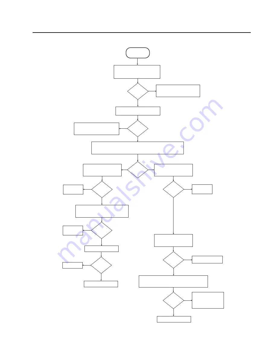
Troubleshooting Charts:
GPS Failure
5-43
5.13 GPS Failure
Verify the location feature is enabled,
replace antenna, and retry in a strong
signal environment (open sky)
The GPS receiver requires a working
antenna, and a direct view of the sky
in order to achieve a position fix
GPS lock?
Yes
No
Check U6101 (CPLD) pin E2 (IO74)
for 32 kHz output, and pin D12 (IO91)
for 1.8V on reset.
START
No GPS Lock
Check for 32 kHz clock at R1318, and
1.8V for GPS reset at R1308
32 kHz and
reset ok?
Yes
Yes
Verify communication with GPS IC by resetting radio while probing R1322 and
R1323 with an oscilloscope. Activity should be seen on both UART test points
for successful comm.
No
Comm.
successful?
Remove Main board shield and
check regulator U1305 for 2.8V
(measured at C1303)
No
Re-flash radio with the latest
released firmware
GPS lock?
Regulator
OK?
Remove Main board shield and check
VBAT voltage for 3.5V (measured at R1313),
and VDDS for 1.8V (measured at R1315)
Radio firmware
was corrupted
No
Yes
Regulators
OK?
No
Yes
Replace faulty
regulator
Check for 26 MHz at C1321
Is 26 MHz
present?
Yes
No
Replace Y1304
Replace GPS IC U1301
Check for 1.8V on LNA enable
measured at C1309
Replace faulty
regulator
No
Yes
1.8V?
Yes
Measure the GPS total front-end gain @ 1575.42 MHz while
GPS IC is active (measured from antenna port to C1324).
Total gain should be approximately 16dB.
Replace GPS IC U1301
No
~18 dB?
Yes
Debug front-end for faulty
component (LNA - U1304,
and SAW filters - FL1301
and FL1303)
No
Replace GPS IC U1301
Summary of Contents for Astro APX 3000
Page 1: ...APXTM TWO WAY RADIOS APX 3000 DETAILED SERVICE MANUAL ...
Page 2: ......
Page 4: ...Notes ...
Page 6: ...vi Document History Notes ...
Page 10: ...x Table of Contents Notes ...
Page 12: ...xii List of Tables Notes ...
Page 18: ...xviii List of Figures Notes ...
Page 22: ...xxii CommercialWarranty Notes ...
Page 46: ...3 20 Theory of Operation Main Board Notes ...
Page 84: ...3 58 Theory of Operation Bluetooth Notes ...
Page 208: ...6 64 Troubleshooting Waveforms LF CW on Spectrum Analyzer Notes ...
Page 222: ...7 14 Troubleshooting Tables List of Board and IC Signals Notes ...
Page 282: ...8 60 Schematics Boards Overlays and Parts Lists Main Board Block UHF1 84012513001_A Notes ...
Page 390: ...8 168 Schematics Boards Overlays and Parts Lists Main Board Block VHF 84012512001_A Notes ...
Page 456: ...9 8 Debugging Fixture Powering up Covert Board Notes ...
Page 468: ...Glossary 10 Glossary Notes ...
Page 472: ...Index 4 Index Notes ...
Page 473: ......


