background image

6-14

Troubleshooting Waveforms:

 TX SSI

6.5

TX SSI 

6.5.1

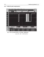
CLK.

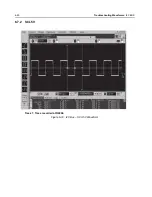
Trace 1: Trace recorded at R2808.

Figure 6-13.  TX SSI – TX CLK. Waveform

Summary of Contents for Astro APX 3000

Page 1: ...APXTM TWO WAY RADIOS APX 3000 DETAILED SERVICE MANUAL ...

Page 2: ......

Page 3: ... products described in this manual may not be copied reproduced modified reverse engineered or distributed in any manner without the express written permission of Motorola Furthermore the purchase of Motorola products shall not be deemed to grant either directly or by implication estoppel or otherwise any license under the copyrights patents or patent applications of Motorola except for the normal...

Page 4: ...Notes ...

Page 5: ...lemented in this manual since the previous edition Edition Description Date 68012007045 A Initial edition Nov 2012 68012007045 B Updated schematics PCB Part list table for UHF1 and updated RX troubleshooting chart pg 5 Feb 2013 68012007045 C Added in new bands VHF UHF2 Jun 2013 ...

Page 6: ...vi Document History Notes ...

Page 7: ...ited Warranty xix Chapter 1 Introduction 1 1 1 1 General 1 1 1 2 Notations Used in This Manual 1 2 Chapter 2 Radio Power 2 1 2 1 General 2 1 2 2 DC Power Routing 2 2 Chapter 3 Theory of Operation 3 1 3 1 Main Board 3 3 3 2 Controller 3 21 3 3 Global Positioning System GPS 3 44 3 4 Accelerometer 3 46 3 5 Bluetooth 3 48 Chapter 4 Troubleshooting Procedures 4 1 4 1 Handling Precautions 4 1 4 2 Recomm...

Page 8: ...hooting Waveforms 6 1 6 1 List of Waveforms 6 1 6 2 Clocks 6 2 6 3 Audio SSI 6 7 6 4 RX SSI 6 11 6 5 TX SSI 6 14 6 6 SPI 6 17 6 7 I2C BUS 6 19 6 8 One Wire 6 22 6 9 GCAI 6 23 6 10 USB 6 25 6 11 SDRAM 6 27 6 12 FLASH CONTROL 6 29 6 13 Receive Baseband Signals 6 34 6 14 GPS 6 35 6 15 Bluetooth Troubleshooting Waveforms 6 38 6 16 Bluetooth Steady State 6 58 6 17 LF CW on Spectrum Analyzer 6 63 Chapte...

Page 9: ... and Display Back 9 3 9 5 Debugging Fixture Set up 9 3 9 6 Board Assembly on Debugging Fixture 9 6 9 7 Powering up Covert Board 9 7 Appendix A Replacement Parts Ordering A 1 A 1 Basic Ordering Information A 1 A 2 Transceiver Board Controller Board and Expander Board Ordering Information A 1 A 3 Motorola Online A 1 A 4 Mail Orders A 1 A 5 Telephone Orders A 1 A 6 Fax Orders A 2 A 7 Parts Identifica...

Page 10: ...x Table of Contents Notes ...

Page 11: ...ower Up Self Check Error Codes 4 4 Table 4 5 Power Up Self Check Diagnostic Actions 4 5 Table 5 1 Troubleshooting Charts 5 1 Table 6 1 List of Waveforms 6 1 Table 6 2 Bluetooth Command to TX 6 38 Table 6 3 Bluetooth Command to RX 6 39 Table 6 4 Low Frequency Command to TX 6 39 Table 6 5 Low Frequency Command to RX 6 39 Table 6 6 Bluetooth Test Points 6 40 Table 7 1 List of Tables of Board and IC S...

Page 12: ...xii List of Tables Notes ...

Page 13: ...MAP Interconnection with Controller Peripherals 3 30 Figure 3 23 OMAP Memory Interface 3 31 Figure 3 24 RX TX SSI Configuration 3 32 Figure 3 25 Audio SSI Configuration 3 33 Figure 3 26 SPI and I2C Configuration 3 34 Figure 3 27 CPLD Block Diagram 3 35 Figure 3 28 Audio TX Path Block Diagram 3 36 Figure 3 29 RX Audio Path Block Diagram 3 37 Figure 3 30 Control Top Block Diagram 3 38 Figure 3 31 GC...

Page 14: ...5 Figure 6 35 GPS RTC Waveforms 6 36 Figure 6 36 GPS UART DATA Waveforms 6 37 Figure 6 37 Summary of Bluetooth Power Up Sequence 6 40 Figure 6 38 Startup Waveforms Vmax of TP16 6 41 Figure 6 39 Startup Timing Difference of TP9 to TP16 6 42 Figure 6 40 Startup Timing Difference of TP5 to TP16 and Voltage Statistics 6 43 Figure 6 41 Startup Timing Difference of TP4 to TP16 and Time Statistics 6 44 F...

Page 15: ...igure 8 22 Connectors 8 24 Figure 8 23 CPLD Circuit 8 25 Figure 8 24 OMAP User Interface Circuit 8 26 Figure 8 25 Memory Interface 8 27 Figure 8 26 Audio Circuit 8 28 Figure 8 27 MAKO DC Distribution Circuit 8 29 Figure 8 28 Serial Interface Circuit 8 30 Figure 8 29 Secure Circuit 8 31 Figure 8 30 Transceiver RF Board Layout Top Side 8 32 Figure 8 31 Transceiver RF Board Layout Bottom Side 8 33 Fi...

Page 16: ...s 8 131 Figure 8 77 GPS Bluetooth Circuit 1 of 2 8 132 Figure 8 78 GPS Bluetooth Circuit 2 of 2 8 133 Figure 8 79 Top Control and JTAG Circuit 8 134 Figure 8 80 Lighting Control Circuit 8 135 Figure 8 81 GCAI and side control 8 136 Figure 8 82 Debugging and Display Connector 8 137 Figure 8 83 Connectors 8 138 Figure 8 84 CPLD Circuit 8 139 Figure 8 85 OMAP User Interface Circuit 8 140 Figure 8 86 ...

Page 17: ... 8 119 MAKO DC Distribution Circuit 8 195 Figure 8 120 Serial Interface Circuit 8 196 Figure 8 121 Secure Circuit 8 197 Figure 8 122 Transceiver RF Board Layout Top Side 8 198 Figure 8 123 Transceiver RF Board Layout Bottom Side 8 199 Figure 9 1 Covert Board Debugging Fixture Front 9 1 Figure 9 2 Covert Board Debugging Fixture Back 9 2 Figure 9 3 Covert Board Debugging Fixtures with Flexes Housing...

Page 18: ...xviii List of Figures Notes ...

Page 19: ...nt between MOTOROLA and the original end user purchaser MOTOROLA does not warrant the installation maintenance or service of the Product MOTOROLA cannot be responsible in any way for any ancillary equipment not furnished by MOTOROLA which is attached to or used in connection with the Product or for operation of the Product with any ancillary equipment and all such equipment is expressly excluded f...

Page 20: ...mproper testing operation maintenance installation alteration modification or adjustment D Breakage or damage to antennas unless caused directly by defects in material workmanship E A Product subjected to unauthorized Product modifications disassemblies or repairs including without limitation the addition to the Product of non Motorola supplied equipment which adversely affect performance of the P...

Page 21: ...of the Product or parts as established by MOTOROLA MOTOROLA will have no liability with respect to any claim of patent infringement which is based upon the combination of the Product or parts furnished hereunder with software apparatus or devices not furnished by MOTOROLA nor will MOTOROLA have any liability for the use of ancillary equipment or software not furnished by MOTOROLA which is attached...

Page 22: ...xxii CommercialWarranty Notes ...

Page 23: ... radio and to help pinpoint the functional problem area In addition you will become familiar with the radio test mode of operation which is a helpful tool If any basic receive or transmit parameters fail to be met the radio should be aligned according to the radio alignment procedure Included in other areas of this manual are functional block diagrams detailed theory of operation troubleshooting c...

Page 24: ...xist and care must be taken and observed NOTE An operational procedure practice or condition that is essential to emphasize CAUTION indicates a potentially hazardous situation which if not avoided might result in equipment damage WARNING indicates a potentially hazardous situation which if not avoided could result in death or injury DANGER indicates an imminently hazardous situation which if not a...

Page 25: ...or the radio is provided through a battery supplying a nominal 7 5 Vdc directly to the transceiver The following battery types and capacities are available Table 2 1 IMPRES Batteries Part Number Description NNTN8305_ IMPRES Li Ion Ultra Slim Battery 1250mAHr NNTN8128_ IMPRES Li Ion Slim Battery 1900mAHr NNTN8129_ IMPRES Li Ion High Capacity Battery FM 2300mAHr PMNN4424_ IMPRES Li Ion High Capacity...

Page 26: ...controls switch Q201 which supplies fuse B to regulator U200 Regulator U201 supplies regulator U202 The 2 775 Vdc supplies regulator U202 Trident IC U702 and 16 8 MHz crystal circuit The 1 85 sets the logic level for the SPI and SSI data In addition the main board also has four regulators 5 Vdc U200 3 Vdc U201 1 8 Vdc U202 and 1 5 Vdc U203 The 5 volt regulator supplies the FGU section transmitter ...

Page 27: ... of the following Main Board contains all transmit receive and frequency generation circuitry including the digital receiver back end IC and the reference oscillator The mainboard also contains a dual core processor which includes both the micro controller unit MCU and a digital signal processor DSP core the processor s memory devices an audio and power supply support integrated circuit IC a digit...

Page 28: ...3 2 Theory of Operation Figure 3 1 APX 3000 Overall Block Diagram Bluetooth Antenna External Accessory Connector Side Control Control Top Main Board RF and GPS Antenna ...

Page 29: ...er Figure 3 2 Figure 3 3 and Figure 3 4 illustrates the UHF1 UHF2 VHF and 700 800 MHz transceiver block diagrams Figure 3 2 Transceiver UHF1 UHF2 Block Diagram Power and Control Omitted FGU Transmitter Receiver 2nd LO Digital RF Atten Antenna Switch coupler Rev Power Detector Log Amp FET TRIDENT IC LOOP FILTER PRESCALAR BUFFER RX SSI Data 16 8MHz BUFFER PRE BUFFER TX LO TX BUFFER TX RX 16 8MHz RX ...

Page 30: ...O Digital RF Atten Antenna Switch coupler Rev Power Detector Log Amp FET TRIDENT IC LOOP FILTER PRESCALAR BUFFER RX SSI Data 16 8MHz BUFFER PRE BUFFER TX LO TX BUFFER TX RX 16 8MHz RX SSI Clock RX SSI Frame Sync Indicates Sub shield Harmonic Filter Driver Amplifier Abacus IF Filter 15dB Step Attn RX VCO TX VCO VHF LNA VHF Mixer GPS ...

Page 31: ...tions are in Table 3 1 Table 3 1 Battery Connector J3 Pin No Signal Description 1 DC_BATT Battery positive terminal nominally 7 5 Vdc 2 Dig_Battery_Data Battery status from battery to controller 3 Ground Battery negative terminal tied to PCB ground FGU Transmitter Receiver 2nd LO Digital RF Atten Antenna Switch coupler Rev Power Detector Log Amp FET TRIDENT IC LOOP FILTER PRESCALAR BUFFER RX SSI D...

Page 32: ...ction is a necessary electrical reference point to complete the antenna circuit path Shields SH1 through SH17 appear on the schematic to show their connection to ground 3 1 2 Receiver The RF signal is received at the antenna and is routed through the Harmonic Filter followed by the Antenna Switch and the 15dB Step Attenuator IC The latter contains a switchable attenuator that is enabled at predete...

Page 33: ...iplexer SSI 18Mhz CLK Abacus III ABACUS III Dec Filter ΣΔ ADC 2nd LO LO CLK Antenna Switch Harmonic Filter 15 dB Step Attenuator VHF VHF IF Filter DIG_CTRL_ATTH Rx LO To GPS Diplexer SSI 18Mhz CLK Abacus III ABACUS III Dec Filter ΣΔ ADC 2nd LO LO CLK 15 dB Step Attenuator Antenna Switch SW DIG_CTRL_ATTH 700 800 700 800 Rx LO IF Filter To GPS Diplexer SW SW SW SSI 18Mhz CLK Abacus III ABACUS III De...

Page 34: ... routed to the first pre selector filter followed by a Low Noise Amplifier LNA and a second pre selector filter Both filters are discrete designs and are used to band limit the incoming energy and suppress known spurious responses such as Image and the IF spur The LNA active device is an NPN transistor U304 with active bias provided by transistor pair Q303 The output of the second pre selector fil...

Page 35: ...s for a listing of transmitter related schematics that will aid in the following discussion The transmitter Figure 3 9 and Figure 3 10 for the UHF1 UHF2 VHF radio consists of one MOSFET high power transistor for the UHF1 UHF2 VHF band The same topology applied for the 700 800 MHz radio Figure 3 11 where one MOSFET high power transistor is used for the 700 800 MHz band The high power transistor is ...

Page 36: ... of FET 2 is pin 6 RFOUT1 Gain control is provided by a voltage applied to pin 1 VCNTRL Typical output power is about 27 dBm 500 mW with VCNTRL at 5 5 V Trident IC Synthesizer Loop Filter TX VCO RX VCO RF Switch Matrix TX Buffer Amp TX Driver Amplifier Transmitter Final FET VHF Harmonic LP Filter Ref Oscillator Antenna Connector Directional Coupler Antenna Switch TO RX GPS Reverse Power Detection ...

Page 37: ...structure The Gate biasing is applied through a biasing network consist of R1603 R1604 R1605 C1615 and C1617 VHF C927 L907 C920 C921 L908 C922 L909 C924 L910 C923 C928 and C925 are theelements of the output matching network apart from a transmission line structure The Gate biasing is applied through a biasing network consist of R903 R904 R905 C915 and C917 700 800 MHz The input impedance matching ...

Page 38: ...UTB Resistors R1121 and R1122 form a voltage divider to set the full scale value of the DAC in this case approximately 1 4V This power set voltage is then fed to the power control IC through the current cutback op amp U1130 and then into a lesser of two voltage decision circuit consisting of U1126 and U1127 This circuit used exclusively in voltage control mode provides the important function of co...

Page 39: ...ching of the TX power control mode from the voltage control loop to the current control loop Comparator U1131 compares the log amp output in voltage control mode to a threshold voltage from DAC C which sets the threshold for handover to current control mode and establishes the upper supply rail for the output of current loop integrator U1104 This threshold is tuned in the factory to correspond to ...

Page 40: ...t injection signals VHF Two VCOs are employed one to generate the first RX LO and the other to generate the transmit injection signals 700 800 MHz Three VCOs are used to cover the entire 700 800 MHz band VCO1 covers the RX 800 MHz band and the TX 700 MHz 764 776 MHz band VCO2 covers the TX 700 800 MHz 794 824 MHz band VCO3 covers the TX 800 MHz 851 870 MHz band and the RX 700 MHz band NOTE Refer t...

Page 41: ... C736 to the Trident IC reference oscillator input This reference is then passed through an internal buffer and is then coupled to the external BJT buffer comprised of U746 and supporting circuitry via C739 These buffers provide isolation for the 16 8 MHz output to the controller circuitry and ABACUS IC Components L753 and C754 form a low pass filter to reduce the harmonics of the 16 8 MHz TRIDENT...

Page 42: ...any voice data and signaling protocols APX 3000 radios must modulate the transmitter carrier frequency over a wide audio frequency range from less than 10 Hz up to more than 6 kHz The Trident IC supports audio frequencies down to zero Hz by using dual port modulation The digital audio signal at pin F11 TXD is transferred to the Trident baseband circuitry via the TX Serial Synchronous Interface SSI...

Page 43: ...ffer input and the other to the prebuffer The output of the prebuffer is then fed to pin 1 RFC of U738 The output of U738 pin 5 RF2 then goes to the attenuator comprised of R703 R704 and R707 and then fed to the receiver section via the RX_LO transmission line To select the UHF TX VCO pin D5 GPO2_TEST2 must be at a high logic level and pin E5 GPO1_TEST1 must be at a low logic level The output of t...

Page 44: ... R707 and then fed to the receiver section via the RX_LO transmission line To select the VHF TX VCO pin D5 GPO2_TEST2 must be at a high logic level and pin E5 GPO1_TEST1 must be at a low logic level The output of the TX VCO is then fed to pin 4 RF1 of switch U3238 The output of U3238 is then split into two signals One to the Prescaler buffer input and the other to the prebuffer The output of the p...

Page 45: ...transmit buffer then goes to the transmit section via the TX_INJ transmission line To select the 700 800 MHz TX VCO pin D5 GPO2 must be at a high logic level and pin E5 GPO1 and pin D6 GPO8 must be at a low logic level The output of the 700 800 MHz TX VCO is then split into two signals One to the Prescaler buffer input and the other to the prebuffer input The output of the prebuffer is then fed to...

Page 46: ...3 20 Theory of Operation Main Board Notes ...

Page 47: ...key distinguishes between a flex connection and a board to board connection A brief description of each of the components is provided below Figure 3 15 Controller Interconnection Diagram 3 2 1 1 Main Controller Components and Connections 3 2 1 1 1 Main Board Controller section The controller section contains the OMAP1710 dual core processor FLASH and SDRAM memory Audio circuitry MAKO and CODEC IC ...

Page 48: ...solid amber upon receive red on PTT and blinking amber on receiver The Bluetooth LED shows fast blinking blue upon waiting to pair and slow blinking blue after paired The solid blue indicates a Bluetooth fatal error 3 2 1 2 1 Top Control Flex The top control consist of an ON OFF switch and a programmable button The flex connect to the main flex through a 12 pin connector 3 2 1 2 2 Side Controls Fl...

Page 49: ... blocks of the controller are DC Distribution Clock Sources Processor Memory CPLD Audio External MAKO User Interfaces GPS BT Chipset TINL5500 FLASH 64MB SDRAM 32MB EMIFF EMIFS UART 2 12C Lighting Controller CPLD EMIFS 32 kHz Clk SSI MACE Secure IC Side Conn GCAI Radio Battery Accessory Audio MAKO IC SPI Side Conn GCAI Codec Accessory Audio Main Board UI GCAI GPS BT Module TINL5500 ATMEL AVR32 RF S...

Page 50: ..._1 4 U6507 1 85 LDO supplies OMAP s IO FLASH CPLD DDR and MACE See Table 3 2 for DC supplies and sources Figure 3 17 Controller DC Block Diagram LDO2 LDO3 SW2 LDO4 LDO6 LDO7 LDO9 LDO10 SW5 VBUS1 VBUS2 External SW TPS62050 MAKO SW_B SW_B SW_B V_SW_3 6 SW1_3 6V SW5_5 4V 1 55V 1 875V V_EXT_1 85 2 23V 2 775V 2 775V 2 775V 3 0V 3 3V LDO8 SW_B 5 0V 5 0V 5 0V EXSW_1 4V 800mA Max 400mA Max 120mA Max 150mA...

Page 51: ...ere the battery supply and on off switch can be accessed MAKO is also responsible for the timing sequence for the enabling of the regulators which is discussed further in section 3 1 3 7 1 and section 3 1 3 7 3 on pages 3 12 and 3 13 Table 3 2 DC Supplies and Sources for Controller V_SW_3 60 V_SW_1 4 V_EXT_1 85 V_SW_5 VBUS1 VBUS2 V_1 875 V_2 75D V_2 775 V_3 0A SW_B OMAP CORE X OMAP IO X DDR X FLAS...

Page 52: ...tic for the V_SW_1 4 regulator Figure 3 18 illustrates the supporting circuitry for the TPS62050 Figure 3 18 V_SW_1 4 Switched Power Supply V_2 775_EXP R6562 LDO Output 2 775 V V_2 8_RF R6564 LDO Output 2 8 V V_5 0A R6565 LDO Output 5 0 V V_3 3 R6566 LDO Output 3 3 V V_3 0A R6567 LDO Output 3 0 V Table 3 3 MAKO s LDO and Supplies Continued Name Ref Description Level V_1 55 10UF 4 7UF C6586M6 C6584...

Page 53: ...on of current saving PFM mode when the radio is in standby mode Figure 3 19 5V Switched Power Supply APX 3000 has Pulse Switching option Mode 1 Pulse Frequency Modulation PFM A relatively noisy but highly efficient pulsing mode for Switched power supplies Mode 2 Pulse Width Modulation PWM Pulsing mode that is cleaner than PFM used when risk of RF interference is present which includes both transmi...

Page 54: ...tor and takes MAKO 24 576 MHz clock and divides it to 32 768 kHz in order to provide for OMAP OMAP starts to power up upon receiving voltages 1 4 V 1 85 V and the 32 768 kHz clock OMAP then activates its 12 MHz clock and releases its reset It then starts to run the boot loader stored in flash A more detailed timing view of the regulators is shown in Figure 3 20 Figure 3 20 Power up Timing Regulato...

Page 55: ...k Recipient Suggested Probe Points Y6501 24 576 MHz Crystal Oscillator MAKO 24 MHz tapped into CPLD U6501 U6101 R6574 Y6502 32 768 kHz Crystal Oscillator MAKO RTC U6501 C6541 Y6601 12 MHz Crystal Oscillator OMAP CPU Clock U6302 C6601 U6302 96 MHz OMAP GPIO DDR Clocks Complementary signals U6301 TP6307 TP6308 U6101 4 096 MHz CPLD GPIO MACE Clock U2510 R6113 U6101 32 768 kHz CPLD GPIO OMAP Boot Up c...

Page 56: ...eyboard Matrix Interface 1 Wire Interface LCD Controller I2C Interface SPI interface External Memory Synchronous Interface External Memory Asynchronous Interface UARTs GPIOs Figure 3 22 Overview of OMAP Interconnection with Controller Peripherals OMAP 1710 Processor FLASH 64 MB Side Conn GCAI GPS BT Chipset TINL5500 CPLD SDRAM 32 MB Audio SSI 1 MACE Secure IC MAKO IC 4 096 MHz Clk Lighting Control...

Page 57: ...down cycles 3 2 4 4 Flash Memory 6304 The Flash memory located in close proximity to the OMAP processor is a 64 MB Numonyx 65nm StrataFlash The flash interface uses 16 data bits and 25 address bits The flash IC is enabled by OMAP processor s CS3 line The flash IC also features a WAIT line that is capable of halting data flow between the processor and flash IC while operating in synchronous read mo...

Page 58: ...nal control signals are also dedicated for the DRAM interface 3 2 4 8 Peripheral Devices The OMAP processor is equipped with multiple buses and interfaces that are configured for peripheral interconnection 3 2 4 8 1 Receive and Transmit SSI These two interfaces are dedicated for communicating with the RF deck digital interface carrying receive and transmit base band signals The OMAP processor gene...

Page 59: ...3 25 Audio SSI Configuration 3 2 4 8 3 ARM SPI This SPI interface is controlled by OMAP s ARM core Devices connected to this bus include MAKO display controllers and the audio CODEC 3 2 4 8 4 DSP SPI This SPI interface is controlled by the DSP core of the OMAP processor This bus is used to configure and control devices on the RF deck OMAP MACE MCBSP1 SSC 0 Black SSC 1 Red BLACK or RED RX RED RX RE...

Page 60: ...acing The four wire UART1 which is capable of hardware flow control is available on the side connector for accessory devices The signals are level translated via MAKO and routed to the side connector via J1 OMAP s UART2 which is a two wire interface capable of software flow control only is connected to the GPS receiver IC on the Main board OMAP 1710 McBSP3 SPIF DSP SPI MAKO TI CODEC ARM SPI I2C LI...

Page 61: ...buffers MAKO s 24 576 MHz clock source is used by the CPLD to generate a 32 768 kHz clock for OMAP booting real time clock timer and for GPS It is also used to generate 4 096 MHz for the MACE IC The CPLD is controlled through OMAP s EMIFS interface It supports 31 configurable GPIOs It also supports 20 input only pins that are accessible through an EMIFS read operation Some of the GPIOs supported b...

Page 62: ... by the TI AIC33 CODEC using the LINE1LP pin on the IC The LINE1LP is multiplexed with the MIC3R within the CODEC and selected as the input when the external microphone path is chosen as the TX audio source The TI CODEC amplifies and samples the external microphone signal The digital data is sent to the OMAP1710 s DSP through the McBSP1 port using the audio SSI bus OMAP DSP MAKO Audio Stereo Codec...

Page 63: ...er path uses the MAKO IC s class AB audio power amplifier to drive 16 Ohm to 28 Ohm external speakers The input to MAKO IC s audio power amplifier is fully differential and comes from the TI CODEC s RIGHT_LOP and RIGHT_LOM The output of the MAKO IC s audio amplifier is also fully differential and available on pins EXT_SPKR_P and EXT_SPKR_M MAKO OMAP DSP SSI MCBSP1 Switch Low Pass Filter 20kHz Corn...

Page 64: ...Off switch is pushed to ON green the switch is grounded and Mech_Sw is pulled low Mech_Sw is an input to MAKO U6501 The logic low input enables an external FET Q6501 gate voltage FET_ENX which switches UN_SW_B to SW_B and turns the radio on The programmable Top Button is by default used for Bluetooth on off It is also biased to 1 875 V R6507 and is an input EMERG_BTN_X to the CPLD and MAKO A butto...

Page 65: ...is used for programming When the OMAP U6501 detects that an accessory has been attached through a logic low on GPIO0 it will identify the device by reading the GCAI_ONE_WIRE line Once the device type is identified the appropriate signals are multiplexed through MAKO to the main flex connector for the particular device Figure 3 31 is a block diagram of the GCAI interface Mounted to the side connect...

Page 66: ...nt P1 PIN ASSIGNMENT SIGNAL 1 GND 7 GCAI_USB_P_GPIO1 5 GCAI_USB_N_GPIO2 3 GCAI_RTS_GPIO_3 11 GCAI_CTS_GPIO_4 17 GCAI_MIC_N 19 GCAI_MIC_P 25 GCAI_SPKR_N 23 GCAI_SPKR_P 9 FCAI_ONE_WIRE 13 GCAI_GPIO0 28 GCAI_VBUS_5V 26 GCAI_VBUS_5V Front View Side View 1 3 5 7 9 11 2 4 6 8 10 12 10 11 20 P1 1 ...

Page 67: ...N ASSIGNMENT SIGNAL 1 GCAI_GPIO0 PwrOn 2 GCAI_ONE_WIRE 3 GCAI_VBUS_5V 4 GCAI_USB_P_GPIO1 TxDc FillReq 5 GCAI_USB_N_GPIO2 RxDc FillData 6 GND 7 GCAI_SPKR_P LineOut 8 GCAI_SPKR_N LineOut 9 GCAI_RTS_GPIO_3 OTG ID FillSen 10 GCAI_MIC_P 11 GCAI_MIC_N 12 GCAI_CTS_GPIO_4 KeyFail FillClk ...

Page 68: ...aces to the main board IC s CPLD OMAP and Audio CODEC NOTE The MACE IC is NOT serviceable The information contained in this section is only intended to help determine whether a problem is due to the MACE IC or the radio itself Figure 3 33 below shows the Encryption architecture for the APX 3000 radio Figure 3 33 APX 3000 Encryption Architecture As shown in Figure 3 33 above the encryption design c...

Page 69: ...0 3 2 7 3 Key Retention The key variables are retained within the MACE IC s memory SRAM or FLASH The keys can be infinite key retention or 30 seconds key retention depending on how the codeplug is set up When set to infinite key retention the keys are stored in the FLASH memory inside the MACE IC When set to 30 second retention the keys are stored in SRAM and will be erased when the radio s batter...

Page 70: ... load to the transceiver Additional GPS diplexing components include L1117 and C1122 which provide proper termination at the transceiver path output to minimize GPS signal leakage at the antenna port tap point at C1314 The GPS signal will then go through a SAW filter FL1301 LNA U1304 and a second SAW filter FL1303 which then connects to the NL5500 s GPS RF input U1301 pin L2 The NL5500 IC is conne...

Page 71: ...z TCXO GPS_nShutdown Input D5 CPLD IO91 U6101 Main Board GPS Reset GPS_UART_TX Output F5 OMAP pin R9 U6302 Main Board GPS UART TX to OMAP UART RX GPS_UART_RX Input E3 OMAP pin M18 U6302 Main Board OMAP UART TX to GPS UART RX LNA_ENABLE Output H6 LNA U1304 Main Board GPS External LNA Enable GPS_LNA_IN Input L2 GPS antenna front end GPS RF Input from antenna GPS IC TI NL5500 GPS_LNA_IN L2 GPS_EXT_LN...

Page 72: ...VR NOTE Please refer to User Guide and CPS for further details Figure 3 35 Accelerometer Block Diagram The registers embedded on the LIS331DL are accessed through SPI serial interface The following pins are responsible for the SPI communication CS is the serial port enable and it is controlled by the AVR SPI Master It goes low at the start of the transmission and toggles high at the end SPC is the...

Page 73: ... 0001 0 CTRL_REG3 rw 22 010 0010 0 CTRL_REG4 rw 23 010 0011 0 CTRL_REG5 rw 24 010 0100 0 HP_FILTER_RESET r 25 010 0101 Dummy register REFERENCE rw 26 010 0110 0 STATUS_REG r 27 010 0111 0 OUT_X_L r 28 010 1000 output OUT_X_H r 29 010 1001 output OUT_Y_L r 2A 010 1010 output OUT_Y_H r 2B 010 1011 output OUT_Z_L r 2C 010 1100 output OUT_Z_H r 2D 010 1101 output Reserved do not modify 2E 2F Reserved ...

Page 74: ... up to 1600 times a second 625 us time slot based on a pseudo random sequence If a packet is not received on one channel the packet will be retransmitted on another channel The Bluetooth feature is accompanied by a Low Frequency LF detection circuit Once a radio has the Bluetooth feature enabled a user can tap their LF enabled Bluetooth audio accessory with the radio at the pairing spot to establi...

Page 75: ...Radio and Accy Power Up Able to pair Initial NFC Pairing Not able to re establish pairing If Link Breaks a appears solid SW tries to re establish connection for x mins Standby Icon flashing Icon no longer Solid b appears Module requires NFC re pairing With radio and accy already on re attempt pairing procedure Refer to Bluetooth pairing flowchart and or User Guide a appears solid Connect sound Dis...

Page 76: ...20 GPIO20 PA21 GPIO21 PB07 GPIO39 PA29 ATMEL AVR32 AT32UC3A0512 PA30 BT_SPARE_DIR D12 D11 E12 F1 C3 A2 B10 D10 J2 M8 VBUS DP DM AUD_CLK AUD_FSTNC AUD_IN AUD_OUT AC_SPKR_UNMUTE_1 8 OPT_BD_DETECT BT_SPARE_1 8 GROUND OPT_BD_GPIO_0_OPT_RST OPT_BD_GPIO_5 OMAP GPIO7 OPT_BD_GPIO_2 OMAP P18 OMAP K15 OPT_BD_GPIO_4 OMAP K14 CPLD GPIO 29 OPT_USB_DP OPT_USB_DM SSI_CLK SSI_FSYNC SSI_BLACK_RX SSI_RED_RX SSI_BLA...

Page 77: ... BT LF signal is applied near the antennas of the BT LF circuitry The Low Frequency block diagram below shows the main connections Figure 3 40 Bluetooth Low Frequency Circuit Block Diagram Figure 3 41 Bluetooth Low Frequency Pairing Data Path LF TX LF Coil LF RX ATMEL AVR32 AT32UC3A0512 SPI0_SCK SCL SDI SDO CS WAKE LF1P LFN 32768 Hz Clock DAT CL_DAT XIN Low Frequency Receiver AS3930 SPI0_MOSI SPI0...

Page 78: ...Output Shown 32KHZ_3 3V R2457 15K C2475 1000PF R2474 270K NFC_ANTENNA OUT C2457 18PF U2412 NL17SZ02 R2475M3 150 USART1_TX R2477 100K 7 16 15 R2419 100 G1 R2476 100K TC1_OCA 4 1 2 TX path GPS_BT_3 3V 12 9 14 6 8 1 2 10 SCL DAT SDO XOUT WAKE NC1 NC2 NC3 VCC CS SDI XIN LFN LF1P VSS GND CTGND C2465 1UF GPS_BT_3 3V U2403M3 AS3930A 51009735001 11 13 5 4 3 RX path NFC_CS_INV C2454 220PF 1 APX 3000 Partia...

Page 79: ... the battery to the Bluetooth related major components sourced by the 3 6V switching regulator on the Main Board Figure 3 44 Current Distribution Tree for Bluetooth Circuitry 7 5V Batt 3 6V Switcher 800mA TPS 62050 2 23V LDO TPS 73601 1 85V LDO LP38693SD J1001 pin 37 VCP_IN TI NL5500 BT GPS 3 3V LDO 500mA LP2989 AS3930A Low Freq ST LIS3331DL Accelerometer Logic Level 8 x Level Shifters 1 x Inverte...

Page 80: ...h IC and the host controller is by a four wire HCI USART0 bus RX TX CTS RTS The Bluetooth IC receives a firmware update over the USART0 each time it is powered on The LF receiver IC transmits its data over the USART1 USART2 is used for displaying debugging messages Table 3 12 Bluetooth Host Processor UART I O Signal Name Pad Name GPIO MUX Function Schematic Name I O USART0 RXD PA00 0 A BT_UART_TX_...

Page 81: ...This SPI bus also communicates with an on board accelerometer The LF transmitter circuit uses a 125 kHz signal U2415 pin M3 that is turned on and off OOK by the USART1_TX signal U2415 pin L12 Table 3 13 SPI I O Signal Name Pad Name GPIO MUX Function Schematic Name I O SPIP NPCS 2 PA09 9 B SPIO_CS2 O SPIP NPCS 0 PA10 10 A NFC_CS O SPIP MISO PA11 11 A SPIO_MISO I SPIP MOSI PA12 12 A SPIO_MOSI O SPIP...

Page 82: ...l Name Pin Name Pad Name Schematic Name I O GPIO19 C12 PA19 USB_BOOT_3 3V I GPIO20 D10 PA20 ATMEL_BOOT I DP D11 BT_AVR_USB_DP I O DM D12 BT_AVR_USB_DM I O VBUS E12 BT_AVR_VBUS I TI NL 5500 Bluetooth GPS ATMEL AVR32 AT32UC3A0512 Low Frequency Receiver AS3930 DAT CL_DAT LF Transmit OR Gate HCI_TX USART0 USART1 USART2 Debug RX Debug TX BT Debug Flex J2401 Connector PB29 K6 Pin 33 Pin 34 Pin 25 Pin 26...

Page 83: ...rap in Flash mode GPIO19 will be used by the Motorola bootloader to trap in Flash mode Both pins are active low The Bluetooth audio is sent over a two channel PCM SSI interface to the audio codec U6405 on the Main board Table 3 15 GPIO I O Signal Name Pad Name GPIO Schematic Name I O GPIO41 PB09 41 BT_HOST_WAKEUP_3 3V I GPIO49 PB17 49 BT_PTT_3 3V O GPIO50 PB18 50 BT_SHUTDOWN_3 3V O GPIO51 PB19 51 ...

Page 84: ...3 58 Theory of Operation Bluetooth Notes ...

Page 85: ...and repair Handling precautions are mandatory for this radio and are especially important in low humidity conditions DO NOT attempt to disassemble the radio without observing the following handling precautions 1 Eliminate static generators plastics Styrofoam etc in the work area 2 Remove nylon or double knit polyester jackets roll up long sleeves and remove or tie back loose hanging neckties 3 Sto...

Page 86: ...equires Vacuum Test Fixture 66012075001 5880384G68 SMA to BNC Adapter Adapts radio s antenna port to BNC cabling of test equipment RVN5224_ Customer Programming Software CPS and Tuner Software CPS allows customer specific programming of modes and features Tuner software required to perform alignment of radio parameters PMKN4012_ Programming Cable Used to program the radio through Customer Programm...

Page 87: ... Output 1 875V V_1 55 R6561 LDO Output 1 55V V_2 775D R6563 LDO Output 2 775V V_2 775_EXP R6562 LDO Output 2 775V V_2 8_RF R6564 LDO Output 2 8V V_5 0A R6565 LDO Output 5 0V V_3 3 R6566 LDO Output 3 3V V_3 0A R6567 LDO Output 3 0V V_EXT_1 85 R6570 LDO Output 1 85V V_SW_1 4 C6570 Switcher Output 1 4V V_SW_3 60 C6561 Switcher Output 3 6V V_2 23 C6573 LDO Output 2 23V Table 4 3 Standard Operating Bia...

Page 88: ...Fatal Error Turn the radio off then on 01 22 Tuning Codeplug Checksum Non Fatal Error Send radio to depot 01 81 Host ROM Checksum Fatal Error Send radio to depot 01 82 FLASH ROM Codeplug Checksum Fatal Error Reprogram the codeplug 01 88 External RAM Fatal Error Note Not a checksum failure Send radio to depot 01 90 General Hardware Failure Fatal Error Turn the radio off then on 01 92 Security Parti...

Page 89: ... resolve the issue send the radio to depot 01 90 Cycle power to radio Continued failure indicates a likely IC failure In this event radio should be sent to the depot for isolation and repair of the problem IC 01 92 The radio should be sent to the depot for reprogramming of the security codeplug 01 93 The radio should be sent to the depot for reflashing of the host code 01 98 Send radio to the depo...

Page 90: ...eck Diagnostics and Repair Not for Field Use Hardware board mismatch then Man Down HW error Updating the firmware should resolve the error message Table 4 5 Power Up Self Check Diagnostic Actions Continued Error Code Error Message Diagnostic Actions ...

Page 91: ...e IC should be checked before replacing the source IC Table 5 1 Troubleshooting Charts Troubleshooting Page No Main Troubleshooting Main Troubleshooting Flowchart 5 3 Power Up Failure Main Board 5 4 B Incorrect Voltage 5 5 Low LDO10 V_3 3 Voltage 5 6 Low LDO3 V_1 55 Voltage 5 7 Low LDO8 V_5 0A Voltage 5 8 Low VBUS2 Voltage 5 9 Low V_SW_1 4 Voltage 5 10 Low V_2 23 Voltage 5 11 Low V_SW_3 6 Voltage ...

Page 92: ...ailure Pairing Issue 5 44 Bluetooth Failure LCD Indication 5 47 PA Failure PA Failure 5 50 PA Failure Page 1 UHF1 UHF2 5 51 PA Failure Page 2 700 800 MHz 5 52 PA Failure Page 3 VHF PA 5 53 PA Failure Page 4 ALC 5 54 Table 5 1 Troubleshooting Charts Continued Troubleshooting Page No ...

Page 93: ... Display Failure 5 19 5 20 or controller power up failure flowchart Chart 5 3 Yes Does the Radio transmit No Go to TX RF troubleshooting Flowchart Chart 5 45 Is there TX deviation Go to controller TX Audio error Chart 5 11 Receive Audio present Go to RX RF controller audio flowchart Chart 5 29 5 11 No No RX SINAD GOOD Buttons Functional No End See Button Test Flowchart Chart 5 10 Yes Yes Yes Yes N...

Page 94: ...lloscope and High Impedance Probe to Measure C6602 Freq 12MHz 1 3 V 1 9 Inspect Y6601 Circuit Repair or Replace Part s Are Parts Solder Connections and Placement Correct No Yes No Yes No Measure Voltage at OMAP_RESET_TP Yes 1 6 V 1 9 OMAP is Out of Reset Proceed to Memory Flow Chart Yes Replace Main Board No Name Ref Description Level V Flow Chart V_1 55 R6561 LDO Output 1 55 10 Low LDO3 V_1 55 Vo...

Page 95: ... at Test Point F_UNSW_B Main Board 6 V 9 Check input and output voltage at F200 Check Voltage at C6593 Controller No Yes 6 V 9 Check Q6501 Circuit and Replace any non Functional Parts Replace Main Board No Yes Replace Connector No Check circuitry from battery contact to fuse Replace any non function part Yes 6 V 9 ...

Page 96: ...sure Radio Current Inspect R6566 Connection Measure SW1 at R6542 Likely MAKO Problem Replace Main Board Is Standby Current more than 15mA above Average 3 3 V 3 9 Is R6566 Soldered Properly Correct R6566 Soldering Proceed to Low V_SW_3 6 Voltage Flow Chart Board has a short Replace Main Board Yes Yes Yes No No No ...

Page 97: ...sure Radio Current Inspect R6561 Connection Measure V_2 23 at R6513 Likely MAKO Problem Replace Main Board Is Standby Current more than 15mA above Average 2 0 V 2 4 Is R6561 Soldered Properly Correct R6561 Soldering Proceed to Low V_2 23 Voltage Flow Chart Board has a short Replace Main Board Yes Yes Yes No No No ...

Page 98: ...ure Radio Current Inspect R6565 Connection Measure Voltage at C6593 Likely MAKO Problem Replace Main Board Is Standby Current more than 15mA above Average 6 0 V 9 0 Is R6565 Soldered Properly Correct R6565 Soldering Proceed to Incorrect B Voltage Flow Chart Board has a short Replace Main Board Yes Yes Yes No No No ...

Page 99: ...5 at C6567 Measure VBUS2 Supply Voltage at R6536 Repair Incorrect Parts Replace Part Replace Board 5 1 V 5 6 Is Part Placed Correctly Are Parts Solder Connections and Placement Correct Check Placement of Q6508 Proceed to Low SW5 Voltage Flow Chart Yes Yes Yes Yes No No No Inspect U6503 and Supporting Circuitry ...

Page 100: ...easure Voltage at C6586 Inspect U6507 and Supporting Circuitry Is Standby Current more than 15mA above Average 1 45 V 1 65 6 V 9 Proceed to Incorrect B Voltage Proceed to Low LD03 V_1 5V Voltage Flow Chart Board has a short Replace Board Yes Yes Yes No No No Are Parts Solder Connections and Placement Correct Replace or Repair Parts Yes No Replace Main Board ...

Page 101: ...Current Measure Voltage at R6542 Inspect U6506 and Supporting Circuitry Replace Board Is Standby Current more than 15mA above Average Are Parts Solder Connections and Placement Correct 3 3 V 3 9 Proceed to Low V_SW_3 6 Voltage Flow Chart Replace or Repair Part s Board has a short Replace Board Yes Yes Yes No No No ...

Page 102: ...Radio Current Measure the Voltage at R6542 Inspect U6504 and All Supporting Circuitry Replace Board Is Standby Current more than 15mA above Average Are Parts Solder Connections and Placement Correct 6 V 9 Proceed to Incorrect B Voltage Replace or Repair Part s Board has a short Replace Board Yes Yes Yes No No No ...

Page 103: ...o Current Is Standby Current more than 15mA above Average Board has a short Replace Board Yes Measure the Voltage at C6593 6 V 9 Proceed to Incorrect B Voltage Inspect U6505 and All Supporting Circuitry Are Parts Solder Connections and Placement Correct Replace or Repair Part s Replace Main Board No No Yes No Yes ...

Page 104: ...6 Proceed to Incorrect V_SW_3 6 Voltage Measure Voltage R6431 on V_5 0A Side No Yes 4 8 V 5 2 Measure Voltage at R6431 on BGAP_COMP side Yes Proceed to Low LD08 V_5 0A Voltage Flow Chart No 2 2 V 2 7 Measure Voltage at R6420 Inspect U6508 and All Supporting Circuitry Yes Yes No Inspect and repair U6409 and Replace Main Board No Are Parts Solder Connections Placement Correct Replace or repair Parts...

Page 105: ...rify if USB accessory is shorting VBUS line Verify L200 C202 and C203 is good Replace accessory or cable Verify SW_B at C6565 Check Q6502 and Q6508 for damage Is 6 V 9 Verify Q6501 Measure BGAP_COMP voltage at R6543 Is 2 2 V 2 7 Check U6505 circuitry If good change U6505 Check BGAP_COMP circuitry Replace defective part Is radio current 100mA Yes Yes Yes Yes Yes No No No No No No No ...

Page 106: ...eplace Fuse Verify UNSW_B at test point F_UNSW_B Verify L200 C202 and C203 is good Verify SW_B at C6524 Is 6 V 9 Verify Q6501 Check U6504 circuitry Enable input present Check U6508 loading V_SW_3 60 MAKO damaged Replace MAKO Is radio current 100mA Check U201 is loading V_SW_3 60 Yes Yes Yes Yes Yes No No No No No ...

Page 107: ... 17 5 4 3 DC Supply 3 Volt Failure Yes Verify DC_LIN_3V at C208 Voltage 3V Yes No Check voltage at C207 Voltage 3 6V Replace U201 No Check for open in branch to troubleshooting section Refer troubleshooting guide 5 4 2 DC supply 3 6V DC_LIN_3V ...

Page 108: ... V 2 7 Check BGAP_COMP circuitry Check for damage to Q6507 Check if U6101 U6405 U6301 and U6304 is draining high current Verify V_SW_3 60 is present at R6510 Replace main board Refer troubleshooting guide 5 4 2 DC supply 3 6V V_EXT_1 85 No Check U6508 circuitry Check BGAP_COMP circuitry Check if U6302 is drawing high current thru E6501 ...

Page 109: ...Failure Yes Verify DC_LIN_1_8V at C210 Voltage 1 8V Yes No Check voltage at C209 Voltage 2 775V Replace U202 No Check for open in branch to troubleshooting section Check voltage at R6564 Yes Replace MAKO Voltage 2 775V No Check continuity between R6564 and C209 DC_LIN_1_8V ...

Page 110: ...e Yes Verify DC_LIN_1_5V at C212 Voltage 1 5V Yes No Check voltage at C210 Voltage 1 8V Refer troubleshooting guide 5 4 5 No Check for open in branch to troubleshooting section Check voltage at C209 Yes Replace U203 Voltage 2 775V No Refer troubleshooting guide 5 4 5 DC_LIN_1_5V ...

Page 111: ... 5V Yes Voltage 1 8V Refer troubleshooting guide 5 4 5 No Verify UNSW_B at test point F_UNSW_B Yes Voltage 2 775V No Check if U6302 draining high current thru E6502 V_SW_1 4 Voltage 1 8V Yes No No Verify L200 C202 and C203 is good No Replace fuse Check external circuitry for U6507 If good change U6507 Yes ...

Page 112: ...tage at the following resistors on the Main board 1 875V each point R4005 PTT R4006 Side button 1 R4007 Side button 2 R6101 Monitor Replace main chassis Button check OK Are the voltages present END Follow troubleshooting guide 5 4 4 Verify buttons enabled in CPS Yes Yes Yes No No No Button check OK Monitor thr voltages at each resistor while pressing the corresponding button The voltages 0V while ...

Page 113: ...or flex with bad connector No View SSI signals at R6606 R6108 with scope Audio Signal Present Audio Signal Present Replace External Speaker Probe Audio signal at SPKR and SPKR test points on main board Yes No No Yes Is data present MAKO might be damaged Change MAKO Is data present No No Yes Replace Main Board Check CODEC Verify ESD protection diode is good by measure voltage drop of diode at GCAI ...

Page 114: ...r Soldered improperly Measure Audio at CODEC C6404 Capacitor Replace Connector Check TX_DA thru R2817 If no signal check CODEC circuitry 4 5 V 4 9 Inspect MIC Bias circuit U6402 and Supporting Circuitry Parts Solder and Placement Correct Is SSI Audio Data Present View SSI Signals at R2807 and R2808 using Oscilloscope Check CODEC or OMAP Replace U6402 Replace parts Yes Yes Yes Yes Yes No No No No N...

Page 115: ...the P1000_4 connector on the GCAI Flex Obtain correct KVL and cable Yes Yes No Yes Verify GCAI data path Check the following signals GPIO4 One Wire Repair connector using programming failure flowchart for details No No Inspect GCAI flex to board connections and Replace GCAI Flex if necessary With KVL attached to the radio and radio on initiate a keyload from the keyloader and look for activity on ...

Page 116: ...DSP and the secure circuitry The secure circuitry is not considered to be field repairable so troubleshooting is limited to verifying a problem with the secure circuitry and replacing the controller if required Use an oscilloscope to verify clocks on main board Signal Probe Point Frequency MACE CLOCK R6113 4 MHz OPT_SSI_CLK R6170 1 5 MHz OPT_SSI_FSYNC R2513 8 KHz Are signals correct No Check SSI c...

Page 117: ...rts if needed No Measure RF levels at the input side of C2305 and pin 3 of U2302 for 7800 radios or the input side of C2605 and pin 3 of U2602 for UHF1 UHF2 radios the input side of C2705 and pin 3 of U2702 for VHF radios Compute the 15dB step attenuator loss Note The 15 dB step attenuator will be enabled Loss 17dB No Yes Yes Testing a 7 800 radio Testing a 700 No Yes 3 4 No Check digital logic to...

Page 118: ...8 Vdc Check Voltage Regulator U200 Replace Q601 Remove SH4 Inspect 2nd LO VCO Replace U602 Repair Defects Visual examination 2nd LO DC bias No No Yes No No Yes Sampling Clock present Signal side of C620 18MHz Check Controller No Yes Yes Yes Measure CLK_SSI_RX output side of R618 DIG_DATA_SSI_RX_FS output side of R616 DIG_DATA_SSI_RX_DOUTA output side of R617 Observe 0 to 1 875 Vdc digital signals ...

Page 119: ...e voltage 1 022 V Collector voltage 0 787 V Emitter voltage 1 561 V Replace UHF1 UHF2 Q1922 VHF Q303 Check DC input line voltages and visually inspect and replace defective components if needed No Yes No Yes Measure RF levels at second preselector filter and compute filter loss UHF1 UHF2 input side of VHF input side of C345 output side of C357 C1959 output side of C1961 Loss 4 dB Check components ...

Page 120: ...o Measure RF levels at the SAW filter FL402 and compute filter loss 700 Output side of R453 and input side of R455 Loss 6 dB No Measure RF levels at the RF switch U405 and compute switch loss 700 output side of R455 input side of C430 Loss 1 dB No Yes Measure RF levels at LNA and compute LNA gain 700 input side of C430 and output side of R412 Gain about 10 dB Yes No Yes Yes Replace FL402 5 7 6 Che...

Page 121: ...o Measure RF levels at the SAW filter FL402 and compute filter loss 800 output side of R452 and input side of R454 Loss 3 dB No Measure RF levels at the RF switch U405 and compute switch loss 800 output side of R454 input side of C430 Loss 1 dB No Yes Measure RF levels at LNA and compute LNA gain 800 input side of C430 and output side of R412 Gain about 8 dB Yes No Yes Yes Replace FL402 5 6 7 Chec...

Page 122: ...Check LNA Check DC bias voltages for U407 at the base pin 1 collector pin 3 Is base voltage 0 778 V and collector voltage 1 552 V Check DC bias voltages of Q403 at the base pin 2 or 5 collector pin 3 emitter pin 4 Is base voltage 1 025 V Collector voltage 0 778 V Emitter voltage 1 552 V Check DC input line voltages and visually inspect and replace defective components if needed No Yes No Yes Repla...

Page 123: ...of L503 For 7800 radios Input of C488 and output of L503 For VHF radios Input of R316 and output of L503 Mixer gain about 0 3dB No Yes 13 8 Note RF Test frequency used UHF1 424 975MHz UHF2 485 075MHz VHF 154 275MHz 700 769 0625MHz 800 860 0625MHz Measured with a High Frequency Probe for relative comparisons and troubleshooting only Actual S21 gain or loss may differ if the test point is not 50 ohm...

Page 124: ...oscilloscope at R616 R617 R618 R616 and R617 belong to U603 and R618 belongs to U604 Note These resistors are not placed You will be probing the pads Repair defects No Yes Yes Is the input side pad of R616 R617 R618 3 V Is the output side pad of R616 R617 R618 1 875 V Replace Abacus U601 Replace level shifters either U603 U604 or both Replace Abacus U601 No Yes No Yes Note RF Test frequency used U...

Page 125: ... Yes No Yes 12 Remove IF filter shield SH1 Check IF filter and LC matching networks Visual inspection OK Repair Defects Replace IF filter FL502 No Yes Note RF Test frequency used UHF1 424 975MHz UHF2 485 075MHz VHF 154 275MHz 700 769 0625MHz 800 860 0625MHz Measured with a High Frequency Probe for relative comparisons and troubleshooting only Actual S21 gain or loss may differ if the test point is...

Page 126: ...are grounded Visually inspect windings Is the polarity correct and all pins are gounded Replace T506 Replace T507 No Yes Yes No Remove shields SH1 SH11 Measure IF level at XTAL filter and compute XTAL filter loss non ground side of C515 and non ground side of C644 Loss 700 6dB 800 6dB UHF1 UHF2 VHF 5dB No problem found 12 No Yes 8 Yes 8 Check FGU and replace U507 if needed No Note RF Test frequenc...

Page 127: ... replace Q767 Check parts around Q785 If OK replace Q785 Is power at C817 20dBm 2 5Vdc at U738 logic pin Is Power 20 dBm 1 5Vdc at L739 0 5 Vdc at pin 3 of Q745 Check 1 5Vdc supply Is power at C740 20dBm Check parts around Q756 If OK replace Q756 Check parts around Q774 If OK replace Q774 Yes No No Check parts around Q745 If OK replace Q745 Yes Yes Yes Check parts around U738 If OK replace U738 Ye...

Page 128: ...er on prescaler buffer output C823 using field probe Remove VCO shield SH15 0 3Vdc or 10 6Vdc or voltage drifting Is power at C823 15dBm VCO locked Check loop filter R701 R705 C703 C707 C713 for continuity fault Replace suspected components Check parts around U702 If OK replace U702 Note Sniff Using an inductive field probe as an antenna to measure frequency Place the probe approximately 1 2 inch ...

Page 129: ...and at Q3156 during Tx Is Vdc at C742 5V Vdc at C726 C734 C737 2 775V Is Vdc at Y701 pin 4 2 775V 16 8MHz at pin 3 of Y701 and C736 16 8MHz at L753 10 8Vdc at pin2 of D723 2 775Vdc at pin 4 of D722 Check and visual inspect U746 circuitry Fault found Check 2 775V and 5V supply Check 2 775V supply Replace Y701 and or C736 Replace the suspected components Replace U702 Check D722 D723 C716 C717 C718 C...

Page 130: ...022 C3023 Y3020 At Tx 851 870MHz Rx 764 776MHz check and visual inspect VR3048 VR3017 VR3020 VR3021 C3050 C3051 C3054 C3055 Y3053 At Tx 794 824MHz check and visual inspect VR3011 VR3004 VR3014 VR3015 C3016 C3017 C3024 C3025 Y3021 Replace U702 Is Vdc at C742 5V Vdc at C726 C734 C737 Is Vdc at Y701 pin 4 2 775V 16 8MHz at pin 3 of Y701 16 8MHz at L753 Yes Yes Yes Yes 2 775Vdc at pin 4 of D722 10 8Vd...

Page 131: ...and at Q3156 during Tx Is Vdc at C742 5V Vdc at C726 C734 C737 2 775V Is Vdc at Y701 pin 4 2 775V 16 8MHz at pin 3 of Y701 and C736 16 8MHz at L753 10 8Vdc at pin2 of D723 2 775Vdc at pin 4 of D722 Check and visual inspect U746 circuitry Fault found Check 2 775V and 5V supply Check 2 775V supply Replace Y701 and or C736 Replace the suspected components Replace U702 Check D722 D723 C716 C717 C718 C...

Page 132: ... and visual inspect D3246 D3249 L3250 C3251 C3252 C3254 L3256 C3258 For Rx Check and visual inspect D3206 D3209 L3210 C3211 C3212 C3214 L3216 C3217 Is Vdc at C742 5V Vdc at C726 C734 C737 2 775V Is Vdc at Y701 pin 4 2 775V 16 8MHz at pin 3 of Y701 and C736 16 8MHz at L753 10 8Vdc at pin2 of D723 2 775Vdc at pin 4 of D722 Check and visual inspect U746 circuitry Fault found Check 2 775V and 5V suppl...

Page 133: ...ccessful comm No Comm successful Remove Main board shield and check regulator U1305 for 2 8V measured at C1303 No Re flash radio with the latest released firmware GPS lock Regulator OK Remove Main board shield and check VBAT voltage for 3 5V measured at R1313 and VDDS for 1 8V measured at R1315 Radio firmware was corrupted No Yes Regulators OK No Yes Replace faulty regulator Check for 26 MHz at C1...

Page 134: ... No Yes BT Button Available No Enable the BT by Toggle the ON programmable button Was the BT Blue LED present Yes In codeplug ensure BT is enabled and there is a button to turn on If Surveilance mode is use the radio will not have a BT blue LED or audio accessory spk indication Check the LCD status through a debugging fixture whether there are any error message been display No Open the radio and c...

Page 135: ...o Yes Pairing Successful No Power Off the POD headset then slightly turn and press firmly on the earpiece connector to ensure it is making good connection to the POD Power on the POD headset and re pair it with the APX radio Yes LF TX Woring See Section 6 17 Figure 6 58 LF RX Woring See Section 6 17 Figure 6 58 Yes Yes No No Replace the NFC Flex and re pair Can the Pairing be Successful No Yes 8 B...

Page 136: ...he components that cause unexpected signals Replace the Potential ICs from OMAP CPLD NL5500 AVR if it causes unexpected signals New issue reflash the BT SW using an SREC file and flashzap If issue still persists change the main board 8 Check the SW compatibility between radio and Accessory Will reload compatible SW or test with a different headset will successful pair with the radio Yes Yes Yes No...

Page 137: ...iled Yes No New or unknown indication Contact SW for detail No Press the BT On Off soft key button to trigger message reload radio SW and retry Clear All Pairing Failed No HW BRD ABSENT Yes Yes HW BRD ABSENT BT ON FAILED No Yes No Yes Try to enable BT again If no button is programmed to turn BT on use CPS to assign for BT On Off Recycle radio and retry BT ON FAILED 5 No BT ON FAILED Reload SW in A...

Page 138: ...tooth Failure Pairing Issue Bluetooth Failure LCD Indication Page 2 7 5 HW BRD FAILED Reload SW in APX radio Enable BT and recycle radio power HW BRD FAILED Non Bluetooth LCD Indication Issue may not be Bluetooth LF NFC Yes No Yes No ...

Page 139: ...routed to different path No Yes No No No Audio heard through side connector accessory without headset paired No Go to RX Audio flowchart 5 6 or External Speaker Audio Out Failure Yes Yes Yes Determine what button is programmed for BT audio re route from the codeplug and press it Audio heard through BT headset No Power off the POD headset then slightly turn and press firmly on the earpiece connecto...

Page 140: ...5 50 Troubleshooting Charts PA Failure 5 15 PA Failure Main Measure Power at several UHF1 UHF2 VHF and 7 800 test frequencies No or Low Power 2 3 VHF 1 UHF1 UHF2 7 800 MHz ...

Page 141: ...s necessary Yes Check L1603 for solderability issues and replace as necessary Was voltage near 3V No Measure the logic inputs of TXH_1 from R1111 and TX_INH from U1138 Yes Trace voltages and check for solderability issues on R1102 Q1101 and Q1103 Replace parts as necessary With the radio in RX mode measure the DC voltage on the drain of Q1601 Was voltage near 7 5V No Check L1606 under shield SH1 f...

Page 142: ...ce as necessary Yes Check L1003 for solderability issues and replace as necessary Was voltage near 3V No Measure the logic inputs of TXH_1 from R1111 and TX_INH from U1138 Yes Trace voltages and check for solderability issues on R1102 Q1101 and Q1103 Replace parts as necessary With the radio in RX mode measure the DC voltage on the drain of Q1001 Was voltage near 7 5V No Check L1007 under shield S...

Page 143: ...s necessary Yes Check L903 for solderability issues and replace as necessary Was voltage near 3V No Measure the logic inputs of TXH_1 from R1111 and TX_INH from U1138 Yes Trace voltages and check for solderability issues on R1102 Q1101 and Q1103 Replace parts as necessary With the radio in RX mode measure the DC voltage on the drain of Q901 Was voltage near 7 5V No Check L906 under shield SH1 for ...

Page 144: ...n4 Yes No Replace U1139 or associated logic Check U6101 or VOCON signal DIG_CTRL_1049 Yes U1142 pin4 1 00V 0 3V No Yes Measure thermal cutback circuit output at U1113 U1114 and U1121 Pin 4 of U1113 U1114 and U1121 at 0V logic low No Check temp sensor U1103 else U1148 Replace log amp U1105 else U1112 else check R1106 for 17 1 Ohm Yes Measure voltage divider at power tuning DAC top of R1121 R1121 ar...

Page 145: ...n be found Table 6 1 List of Waveforms Waveform Page No Clocks 32 kHz Clock 6 2 4 MHz Clock 6 3 12 MHz Clock 6 4 16 8 MHz Clock 6 5 24 MHz Clock 6 6 Audio SSI Red Tx 6 7 Red Rx 6 8 SYNC 6 9 BCLK 6 10 RX SSI CLK 6 11 DA 6 12 FSYNC 6 13 TX SSI CLK 6 14 DA 6 15 FSYNC 6 16 SPI CLK 6 17 CS 6 18 I2C BUS SCL 6 19 SCL 5V 6 20 SDA 6 21 One Wire 1 Wire 6 22 GCAI GPIO0 6 23 GPIO4 Keyfail during Keyload 6 24 ...

Page 146: ...6 2 Troubleshooting Waveforms Clocks 6 2 Clocks 6 2 1 32 kHz Clock Trace 1 Trace recorded at R6115 Figure 6 1 32 kHz Clock Waveform ...

Page 147: ...Troubleshooting Waveforms Clocks 6 3 6 2 2 4 MHz Clock Trace 1 Trace recorded at R6113 Figure 6 2 4 MHz Clock Waveform ...

Page 148: ...6 4 Troubleshooting Waveforms Clocks 6 2 3 12 MHz Clock Trace 1 Trace recorded at C6601 Figure 6 3 12 MHz Clock Waveform ...

Page 149: ...Troubleshooting Waveforms Clocks 6 5 6 2 4 16 8 MHz Clock Trace 1 Trace recorded at R6217 Figure 6 4 16 8 MHz Clock Waveform ...

Page 150: ...6 6 Troubleshooting Waveforms Clocks 6 2 5 24 MHz Clock Trace 1 Trace recorded at C6592 Figure 6 5 24 MHz Clock Waveform ...

Page 151: ...Troubleshooting Waveforms Audio SSI 6 7 6 3 Audio SSI 6 3 1 Red Tx Trace 1 Trace recorded at R6618 Figure 6 6 Audio SSI Red Tx Waveform ...

Page 152: ...6 8 Troubleshooting Waveforms Audio SSI 6 3 2 Red Rx Trace 1 Trace recorded at R1332 Figure 6 7 Audio SSI Red Rx Waveform ...

Page 153: ...Troubleshooting Waveforms Audio SSI 6 9 6 3 3 SYNC Trace 1 Trace recorded at Pin 30 of J2301 Figure 6 8 Audio SSI Sync Waveform ...

Page 154: ...6 10 Troubleshooting Waveforms Audio SSI 6 3 4 BCLK Trace 1 Trace recorded at R6107 Figure 6 9 Audio SSI BCLK Waveform ...

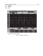
Page 155: ...Troubleshooting Waveforms RX SSI 6 11 6 4 RX SSI 6 4 1 CLK Trace 1 Trace recorded at R2806 Figure 6 10 RX SSI CLK Waveform ...

Page 156: ...6 12 Troubleshooting Waveforms RX SSI 6 4 2 DA Trace 1 Trace recorded at R2805 Figure 6 11 RX SSI DA Waveform ...

Page 157: ...Troubleshooting Waveforms RX SSI 6 13 6 4 3 FSYNC Trace 1 Trace recorded at R2804 Figure 6 12 RX SSI FSync Waveform ...

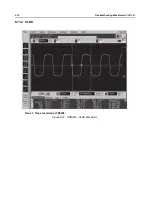
Page 158: ...6 14 Troubleshooting Waveforms TX SSI 6 5 TX SSI 6 5 1 CLK Trace 1 Trace recorded at R2808 Figure 6 13 TX SSI TX CLK Waveform ...

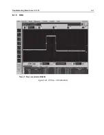
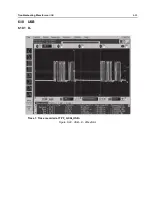
Page 159: ...Troubleshooting Waveforms TX SSI 6 15 6 5 2 DA Trace 1 Trace recorded at R2817 Figure 6 14 TX SSI DA Waveform ...

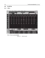
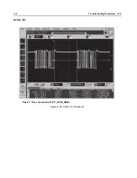
Page 160: ...6 16 Troubleshooting Waveforms TX SSI 6 5 3 FSYNC Trace 1 Trace recorded at R2807 Figure 6 15 TX SSI FSync Waveform ...

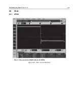
Page 161: ...Troubleshooting Waveforms SPI 6 17 6 6 SPI 6 6 1 CLK Trace 1 Trace recorded at R2803 Figure 6 16 SPI CLK Waveform ...

Page 162: ...6 18 Troubleshooting Waveforms SPI 6 6 2 CS Trace 1 Trace recorded at R6602 Figure 6 17 CS Waveform ...

Page 163: ...Troubleshooting Waveforms I2C BUS 6 19 6 7 I2C BUS 6 7 1 SCL Trace 1 Trace recorded at R6208 Figure 6 18 I2C Bus SCA Waveform ...

Page 164: ...6 20 Troubleshooting Waveforms I2C BUS 6 7 2 SCL 5V Trace 1 Trace recorded at R2204 Figure 6 19 I2C Bus SCA 5V Waveform ...

Page 165: ...Troubleshooting Waveforms I2C BUS 6 21 6 7 3 SDA Trace 1 Trace recorded at R6209 Figure 6 20 I2C Bus SDA Waveform ...

Page 166: ...6 22 Troubleshooting Waveforms One Wire 6 8 One Wire 6 8 1 1 Wire Trace 1 Trace recorded at R4009 Figure 6 21 1 Wire Waveform ...

Page 167: ...Troubleshooting Waveforms GCAI 6 23 6 9 GCAI 6 9 1 GPIO0 Trace 1 Trace recorded at D4001 test point GPIO0 Figure 6 22 GCAI GPIO0 Waveform ...

Page 168: ...6 24 Troubleshooting Waveforms GCAI 6 9 2 GPIO4 Keyfail during Keyload Trace 1 Trace recorded at P2001_21 or R2005 or C2006 DNP Figure 6 23 GCAI GPIO4 Waveform ...

Page 169: ...Troubleshooting Waveforms USB 6 25 6 10 USB 6 10 1 D Trace 1 Trace recorded at TP F_GCAI_USB Figure 6 24 USB D Waveform ...

Page 170: ...6 26 Troubleshooting Waveforms USB 6 10 2 D Trace 1 Trace recorded at TP F_GCAI_USB Figure 6 25 USB D Waveform ...

Page 171: ...Troubleshooting Waveforms SDRAM 6 27 6 11 SDRAM 6 11 1 CLK Trace 1 Trace recorded at TP6307 Figure 6 26 SDRAM CLK Waveform ...

Page 172: ...6 28 Troubleshooting Waveforms SDRAM 6 11 2 CLKX Trace 1 Trace recorded at TP6308 Figure 6 27 SDRAM CLKX Waveform ...

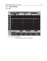
Page 173: ...Troubleshooting Waveforms FLASH CONTROL 6 29 6 12 FLASH CONTROL 6 12 1 ADV Trace 1 Trace recorded at R6314 Figure 6 28 FLASH CONTROL ADV Waveform ...

Page 174: ...6 30 Troubleshooting Waveforms FLASH CONTROL 6 12 2 CS3 Trace 1 Trace recorded at R6311 Figure 6 29 FLASH CONTROL CS3 Waveform ...

Page 175: ...Troubleshooting Waveforms FLASH CONTROL 6 31 6 12 3 OE Trace 1 Trace recorded at R6312 Figure 6 30 FLASH CONTROL OE Waveform ...

Page 176: ...6 32 Troubleshooting Waveforms FLASH CONTROL 6 12 4 RDY Trace 1 Trace recorded at R6316 Figure 6 31 FLASH CONTROL RDY Waveform ...

Page 177: ...Troubleshooting Waveforms FLASH CONTROL 6 33 6 12 5 WE Trace 1 Trace recorded at R6313 Figure 6 32 FLASH CONTROL WE Waveform ...

Page 178: ...shooting Waveforms Receive Baseband Signals 6 13 Receive Baseband Signals Trace 1 DIG_DATA_SSI_RX_FS at R616 Trace 2 DIG_DATA_SSI_RX_DOUTA at R617 Trace 3 CLK_SSI_RX at R618 Figure 6 33 Received Baseband Waveforms ...

Page 179: ...Troubleshooting Waveforms GPS 6 35 6 14 GPS 6 14 1 GPS TCXO 26 MHz TCXO Trace 1 Trace recorded at C1321 at Main Board Figure 6 34 GPS TCXO Waveforms ...

Page 180: ...6 36 Troubleshooting Waveforms GPS 6 14 2 GPS RTC GPS 32 kHz RTC Trace 1 Trace recorded at R1318 of Main Board Figure 6 35 GPS RTC Waveforms ...

Page 181: ...Troubleshooting Waveforms GPS 6 37 6 14 3 GPS UART RX TX Data Trace 1 Trace recorded at R1322 TX R1323 RX of Main Board Figure 6 36 GPS UART DATA Waveforms ...

Page 182: ...he antenna during testing The following is the procedure to activate the Bluetooth LF transmitter or receiver using RCMP commands To send an RCMP command connect a RS 232 com port GCAI cable between the radio and PC Start HyperTerminal on com 1 typical RS 232 port using these settings 9600 baud 8 bit non parity stop bit 1 HW flow control Type AT DEBUG then type rcmpraw 000c Bluetooth Command to TX...

Page 183: ...by a signal generator by tapping on C2454 or C2457 The result contains the LF RSSI This command is not in the initial SW release but is included in SR 7 11 SW If no signal is detected the response will be 8039010305 A fast verification that requires no additional test equipment can be done by sending the LF TX command then the LF RX command directly afterwards If both the transmitter and receiver ...

Page 184: ...13 BT_AVR_RESET BT AVR Reset 1 85 1 73 9 R6705 VCC_1 85 VCC 1 85 1 85 1 86 10 TP2417 USB_BOOT_1 8V USB Boot 1 8V 1 8 1 81 11 TP2466 ATMEL_BOOT Atmel Boot 3 3 3 04 12 M1 GND Ground 0 13 R6563 V_2 755D VCC 2 775 2 775 2 74 14 TP2414 BT_AVR_USB_DP USB 3 3 3 43 15 TP2415 BT_AVR_USB_DM USB 3 3 3 47 16 R6542 V_SW_3 6 VSW 3 6 3 51 3 49 17 R1318 R2407 32KHZ 32 kHz clock 1 85 1 87 Voltage V Net Name V_SW_3...

Page 185: ...Troubleshooting Waveforms Bluetooth Troubleshooting Waveforms 6 41 6 15 2 Bluetooth Startup Vmax of TP16 Figure 6 38 Startup Waveforms Vmax of TP16 ...

Page 186: ...6 42 Troubleshooting Waveforms Bluetooth Troubleshooting Waveforms 6 15 3 Bluetooth Startup Timing Difference of TP9 to TP16 Figure 6 39 Startup Timing Difference of TP9 to TP16 ...

Page 187: ...ting Waveforms Bluetooth Troubleshooting Waveforms 6 43 6 15 4 Bluetooth Startup Timing Difference of TP5 to TP16 and Voltage Statistics Figure 6 40 Startup Timing Difference of TP5 to TP16 and Voltage Statistics ...

Page 188: ...ubleshooting Waveforms Bluetooth Troubleshooting Waveforms 6 15 5 Bluetooth Startup Timing Difference of TP4 to TP16 and Time Statistics Figure 6 41 Startup Timing Difference of TP4 to TP16 and Time Statistics ...

Page 189: ...shooting Waveforms Bluetooth Troubleshooting Waveforms 6 45 6 15 6 Bluetooth Startup Timing Difference of TP4 to TP5 and Time Statistics Figure 6 42 Startup Timing Difference of TP4 to TP5 and Time Statistics ...

Page 190: ...6 46 Troubleshooting Waveforms Bluetooth Troubleshooting Waveforms 6 15 7 Bluetooth Startup Vmax of TP5 and Time Statistics Figure 6 43 Startup Vmax of TP5 and Time Statistics ...

Page 191: ...Troubleshooting Waveforms Bluetooth Troubleshooting Waveforms 6 47 6 15 8 Bluetooth Startup Vmax of TP4 and Time Statistics Figure 6 44 Startup Vmax of TP4 and Time Statistics ...

Page 192: ...6 48 Troubleshooting Waveforms Bluetooth Troubleshooting Waveforms 6 15 9 Bluetooth Startup Vmax of TP5 and Voltage Statistics Figure 6 45 Startup Vmax of TP5 and Voltage Statistics ...

Page 193: ...Troubleshooting Waveforms Bluetooth Troubleshooting Waveforms 6 49 6 15 10Bluetooth Startup Vmax of TP9 and Voltage Statistics Figure 6 46 Startup Vmax of TP9 and Voltage Statistics ...

Page 194: ...6 50 Troubleshooting Waveforms Bluetooth Troubleshooting Waveforms 6 15 11 Bluetooth Startup Vmax of TP10 and Time Statistics Figure 6 47 Startup Vmax of TP10 and Time Statistics ...

Page 195: ...Troubleshooting Waveforms Bluetooth Troubleshooting Waveforms 6 51 6 15 12 Bluetooth Startup Vmax of TP16 and Voltage Statistics Figure 6 48 Startup Vmax of TP16 and Voltage Statistics ...

Page 196: ...6 52 Troubleshooting Waveforms Bluetooth Troubleshooting Waveforms 6 15 13 Bluetooth Startup Vmax of TP13 and Voltage Statistics Figure 6 49 Startup Vmax of TP13 and Voltage Statistics ...

Page 197: ...Troubleshooting Waveforms Bluetooth Troubleshooting Waveforms 6 53 6 15 14 Bluetooth Startup Vmax of TP11 and Voltage Statistics Figure 6 50 Startup Vmax of TP11 and Voltage Statistics ...

Page 198: ...bleshooting Waveforms Bluetooth Troubleshooting Waveforms 6 15 15 Bluetooth Startup Timing Difference of TP13 to TP16 and Time Statistics Figure 6 51 Startup Timing Difference of TP13 to TP16 and Time Statistics ...

Page 199: ...ooting Waveforms Bluetooth Troubleshooting Waveforms 6 55 6 15 16 Bluetooth Startup Timing Difference of TP10 to TP13 and Time Statistics Figure 6 52 Startup Timing Difference of TP10 to TP13 and Time Statistics ...

Page 200: ...bleshooting Waveforms Bluetooth Troubleshooting Waveforms 6 15 17 Bluetooth Startup Timing Difference of TP11 to TP13 and Time Statistics Figure 6 53 Startup Timing Difference of TP11 to TP13 and Time Statistics ...

Page 201: ...Troubleshooting Waveforms Bluetooth Troubleshooting Waveforms 6 57 6 15 18 Bluetooth CW on Spectrum Analyzer Figure 6 54 Bluetooth CW on Spectrum Analyzer ...

Page 202: ...6 58 Troubleshooting Waveforms Bluetooth Steady State 6 16 Bluetooth Steady State 6 16 1 Waveforms USB D Vmax and Packet Timing with Statistics Figure 6 55 USB D Vmax and Packet Timing with Statistics ...

Page 203: ...Troubleshooting Waveforms Bluetooth Steady State 6 59 6 16 2 Waveforms USB D Vmax and Packet Timing with Statistics Figure 6 56 USB D Vmax and Packet Timing with Statistics ...

Page 204: ...6 60 Troubleshooting Waveforms Bluetooth Steady State 6 16 3 Waveforms V_SW_3 6 Voltage Statistics Figure 6 57 V_SW_3 6 Voltage Statistics ...

Page 205: ...Troubleshooting Waveforms Bluetooth Steady State 6 61 6 16 4 Waveforms 32 kHz clock Vmax with Statistics Figure 6 58 32 kHz clock Vmax with Statistics ...

Page 206: ...orms Bluetooth Steady State 6 16 5 Waveforms LF Coil with TX and RX Figure 6 59 LF Coil when TX and RX Data taken from LF inductor contact at C2454 or C2457 while pairing with a headset TX Voltage can be as high as 40V OOK used ...

Page 207: ...Troubleshooting Waveforms LF CW on Spectrum Analyzer 6 63 6 17 LF CW on Spectrum Analyzer Figure 6 60 LF CW on Spectrum Analyzer ...

Page 208: ...6 64 Troubleshooting Waveforms LF CW on Spectrum Analyzer Notes ...

Page 209: ... signals Table 7 1 lists and provides links to each of the tables in this chapter Table 7 1 List of Tables of Board and IC Signals Table No Table Name Page No 7 2 Mainboard to main flex connector interface Pin Out 7 2 7 3 Main Flex connector to main board connector interface Pin Out 7 3 7 4 Side Button Flex connector Pin Out 7 4 7 5 Top Control Flex connector Pin Out 7 4 7 6 NFC Flex connector int...

Page 210: ...J1 5 R4006 UP_ARROW_BUTTON J1 6 F_GCAI_USB GPIO_1_DP_TXDC_FILLREQ J1 7 R4007 DOWN_ARROW_BUTTON J1 8 F_GCAI_1WIRE GCAI_1WIRE_5V J1 9 C2331 TOP_SIDE_BUTTON J1 10 R2358 GPIO_4_CTS_KEYFAIL_FILLCLK J1 11 TP6210 ON_OFF_SWITCH J1 12 F_Vbus2 VBUS2 J1 13 C2115 TOP_BUTTON J1 14 F_Vbus2 VBUS2 J1 15 Chassis GND J1 16 Gpio0 GPIO_0 J1 17 Chassis GND J1 18 None EXT_MIC_NEG_DP J1 19 SPKR EXT_SPKR_NEG_DP J1 20 TP6...

Page 211: ...O3 P1 3 MIDDLE_SIDE_BUTTON P1 4 Gcai_USB_N_Gpio2 P1 5 UP_ARROW_BUTTON P1 6 Gcai_USB_P_Gpio1 P1 7 DOWN_ARROW_BUTTON P1 8 Gcai_one_wire P1 9 TOP_SIDE_BUTTON P1 10 Gcai_Gpio4_cts P1 11 ON_OFF_SWITCH P1 12 Gcai_Vbus_5V P1 13 Emerg_Btn P1 14 Gcai_Vbus_5V P1 15 GND P1 16 Gcai_GPIO0 P1 17 GND P1 18 EXT_MIC_NEG_DP P1 19 GCAI_EXT_SPKR_N P1 20 EXT_MIC_POS_DP P1 21 GCAI_EXT_SPKR_P P1 22 GND P1 23 GND P1 24 ...

Page 212: ...est Place Main Board Signal Name Pin GND P1 1 Top_Arrow_Button P1 2 GND P1 3 Middle_Arrow_Button P1 4 GND P1 5 Up_Arrow_Button P1 6 GND P1 7 Down_Arrow_Button P1 8 GND P1 9 GND P1 10 Test Place Main Board Signal Name Pin GND P1 1 GND P1 2 On_Off_switch P1 3 Top_Button P1 4 GND P1 5 GND P1 6 GND P1 7 GND P1 8 GND P1 9 GND P1 10 GND P1 11 GND P1 12 ...

Page 213: ...eset Direction PU State Direction PU or PD NC NC M8 Output 0 Output codec_cs DSP SPI chip select for TI dual CODEC Y1 0 Output 1 Output abacus_cs DSP SPI chipselect for Abacus IC L3 0 Output 0 Output trident_cs DSP SPI chipselect for Trident IC V6 0 Output 0 Output synthesizer_lock RF synthesizer lock detect V15 1 Lock Input None Input None f2_timer_dmcs Timer output compare for DMCS or SYNCB M20 ...

Page 214: ...GPIO3 AA15 Input None 0 Output gcai_gpio4 GPIO4 R14 Input None Input Pull down bluetooth_ptt PTT signal from Blue tooth AVR Y5 0 Pressed Input Pullup Input Pull down f2_timer_input_ca pture Receives one of three timing signals mux ed through CPLD Abacus Sync DMCS Ramp DAC Trigger P20 Input Pull down Input Pull down bt_avr_status AVR status read by OMAP P18 Input Pullup Input Pull down enc_wakeup M...

Page 215: ...utput gps_shutdown Shutdown to GPS D12 0 Output 0 Output rf_reset Reset to RF board A8 0 Output 0 Output Unused and Unwired OMAP Pin B7 Output 0 Output Unused and Unwired OMAP Pin B8 Output 1 Output C7 0 Output None 1 Output None Unused and Unwired OMAP Pin J2 Input None Input None Unused and Unwired OMAP Pin M8 Input None Input None bt_usb_boot Bluetooth boot signal P8 0 Output None Input None bt...

Page 216: ...ion identifier bit 1 REG Register Register cpld_ver0 CPLD version identifier bit 0 REG Register Register board_id8 Controller Board ID bit 8 H12 Input Pullup Input Pullup board_id7 Controller Board ID bit 7 H13 Input Pullup Input Pullup board_id6 Controller Board ID bit 6 G13 Input Pullup Input Pullup board_id5 Controller Board ID bit 5 F13 Input Pullup Input Pullup board_id4 Controller Board ID b...

Page 217: ...lled low on PCB mode 0 P12 Input None 0 Input None mako_resetx Master cold reset input for entire 1710 chip controlled by Mako IC R12 0 Input None Input None mako_resetx MPU ARM9 subsys tem reset input tied to PWRON_RESET R12 on PCB U20 0 Input None Input None omap_reset Reset output from OMAP used for CODEC CPLD Front Display Lighting Controllers MACE Tamper ckt AA20 0 Output None 0 Output None N...

Page 218: ... None 0 Output Pull down usb1_se0 USB1 Bidirectional Single Ended Zero R13 I O None U Output Pull down usb0_txen USB0 Transmit Enable W4 0 Output None 1 Output Pull down usb0_data USB0 Bidirectional Data P9 I O None Input None usb0_se0 USB0 Bidirectional Single Ended Zero R8 I O None Input None ssi_omap_clock SSI Clock into OMAP G21 Input None Input None ssi_omap_sync SSI Sync into OMAP H15 Input ...

Page 219: ...t SSI Frame Sync from RF Board W7 Input Pull down Input Pull down trident_ssi 2 Transmit SSI Data from OMAP AA5 Output Pull down 0 Output Pull down abacus_ssi 0 Receive SSI Clock from RF Board V7 I O Pull down Input None abacus_ssi 1 Receive SSI Frame Sync from RF Board W6 I O Pull down Input None abacus_ssi 2 Receive SSI Data from RF Board P10 Input Pull down Input Pull down scl I2C Clock T18 I O...

Page 220: ...Data in from JTAG box to Controller Y19 Input Input Pull down nemu0 Emulation pin 0 not used pulled high on PCB V16 I O Input Pullup nemu1 Emulation pin 1 not used pulled high on PCB W17 I O Input Pullup Table 7 7 Overall GPIO pin functions Continued Signal Name Description Pin or Ball Active State SW Initialized HW Reset Direction PU State Direction PU or PD ...

Page 221: ...ontroller U2205 MAIN BOARD top side BLUETOOTH GPS Combination IC U1301 MAIN BOARD bottom side BlueTooth AVR processor U2415 MAIN BOARD top side SDRAM U2413 MAIN BOARD top side Accelerometer U2416 MAIN BOARD bottom side Battery contact springs M101 MAIN BOARD bottom side VCO UHF1 Q3123 MAIN BOARD bottom side VCO UHF1 Q3156 MAIN BOARD bottom side VCO 7800 Q3038 MAIN BOARD bottom side VCO 7800 Q3039 ...

Page 222: ...7 14 Troubleshooting Tables List of Board and IC Signals Notes ...

Page 223: ...rcuit 8 25 OMAP User Interface Circuit 8 26 Memory Interface 8 27 Audio Circuit 8 28 MAKO DC Distribution Circuit 8 29 Serial Interface Circuit 8 30 Secure Circuit 8 31 700 800 MHz 84012501002 Main Board Block 8 61 Transceiver RF Board Overall Schematic 8 62 Receiver Back End 8 64 Frequency Generation Unit Circuit 1 of 2 8 65 Frequency Generation Unit Circuit 2 of 2 8 65 Automatic Level Control Ci...

Page 224: ...plifier Circuit 8 173 Automatic Level Control Circuit 8 174 Receiver Front End Circuit 8 175 Receiver Back End Mixer 8 176 Receiver Back End 8 177 Receiver VCO Circuit 8 178 Table 8 1 List of Transceiver Schematics and Board Overlays Continued Transceiver Board Schematic Board Layout Page No Transmitter VCO Circuit 8 179 Frequency Generation Unit Circuit 1 of 2 8 180 Frequency Generation Unit Circ...

Page 225: ...TX_INHIBIT V_2 8_RF V_EXT_1 85 V_SW_3 60 ISET ABACUS_SPI_CS 16 8_MHZ_SINEWAVE UNSW_B TX_FSYNC_CONN TX_CLK_CONN RX_DA_CONN RX_FSYNC_CONN SPI_DSP_MISO F2_DMCS BAT_STATUS LOCK_DET_A RX_CLK_CONN SPI_DSP_MISO ISET RF_ANT TX_INHIBIT V_2 8_RF V_EXT_1 85 V_SW_3 60 UNSW_B BAT_STATUS 16 8_MHZ_SINEWAVE ABACUS_SPI_CS F2_PARAMP F2_SYNCB RF_BRD_RSTB RF_DAC_SPI_CS TX_FSYNC TX_CLK RX_FSYNC LOCK_DET SPI_DSP_CLK SP...

Page 226: ...N_5V DC_LIN_3V DIG_CTRL_I_LIMIT DIG_CTRL_ATTH TL_RX_UHF1_FE_IN ANA_RX_FE_TUNE DIG_CTRL_RXU DC_LIN_1_8V_A IF IF IF IF12 IF13 IF15 DC_LIN_1_8V 1 1 1 covert_rxfe_uhf1 SUBDESIGN_SUFFIX 20 RF_RX_UHF1_FE_OUT IF IF24 DC_LIN_5V 1 DC_LIN_5V TL_RX_LO TL_RX_MIX_IN SUBDESIGN_SUFFIX 21 covert_mixer CLK_16_8_MHZ DC_LIN_1_875V_D DC_LIN_3V DC_LIN_5V DIG_CTRL_SPI_PC DIG_CTRL_SPI_PE DIG_DATA_SPI_PD DIG_RX_SYNCB TL_...

Page 227: ...02M13 100PF UPP9401E3 IF IF2607M13 D2603M13 C2604M13 RF_OUT 1 OUT 3 6PF 18 9NH 4 3PF C2608M13 L2601M13 C2607M13 68PF 82 82 82 R2602M13 C2602M13 R2603M13 R2604M13 UPP9401E3 100PF D2602M13 C2601M13 100PF MMBD352 D2601M13 C2605M13 3 2 1 IF IF2606M13 RX_IN 1 OUT 0 DNP R2601M13 RFIO1 RFIO2 GND V1 V2 AT267 100PF C2606M13 U2602M13 5 4 3 1 2 VCC GND 1UF NC7WZ04 NC7WZ04 U2601M13 U2601M13 C2609M13 DC_LIN_3V...

Page 228: ...F1 84012513001_A Figure 8 4 Transmitter HF Circuit IF IF1801M17 RF_OUT 1 IN 3 6PF 5PF 13 7NH C1803M17 C1804M17 L1803M17 4 7PF 13 7NH 3 3PF C1807M17 L1809M17 C1820M17 2 2PF 13 7NH 7 5PF L1811M17 C1821M17 C1826M17 1 8PF 100PF C1827M17 C1822M17 IF IF1802M17 HF_OUT 1 OUT ...

Page 229: ... 100PF 110NH C1607M16 L1603M16 C1611M16 C1608M16 2 1 3 9NH 5 6PF 33PF L1604M16 C1613M16 C1610M16 3 9NH 39PF 47PF 68PF DNP L1605M16 C1616M16 C1614M16 C1633M16 D G S1 S2 RD07MUP2B 150 15PF Q1601M16 R1606M16 C1619M16 4 2 1 3 2 1 23 75NH L1606M16 2 1 01UF 100PF DNP C1618M16 C1634M16 IF IF1652M16 VC 1 IN 9 1K R1601M16 LMV841 U1601M16 2 5 4 1 3 DNP 100PF 01UF C1612M16 C1605M16 10K R1602M16 3300PF 100PF ...

Page 230: ...0PF C1163M11 R1202M11 C1168M11 C1164M11 R1101M11 U1137M11 DC_LIN_1_85 DC_LIN_1_875V_D DC_LIN_5V DIG_SPI_CLK ANA_CTRL_VSET B1 C1 B2 C2 D2 D1 A1 A2 IN IN IN SN74LVC2T45 U1138M11 DC_LIN_1_875V_D DIG_DATA_SPI_MOSI DC_LIN_5VREF DC_LIN_5V DIG_CTRL_TX_INH A1 A2 VCCA VCCB GND B1 B2 DIR TX_INH B1 C1 B2 C2 D2 D1 A1 A2 VCC GND VCC GND 74LVC1G08YZP 74LVC1G32YZP U1147M11 U1146M11 DC_LIN_1_875V_D C1 A2 C1 A2 74...

Page 231: ...1901M20 ANA_RX_FE_TUNE 1 IN IF INPORT IF1900M20 TL_RX_UHF1_FE_IN 1 IN 10K 1SV305 10PF 18NH 5 6PF 3 6NH L1908M20 R1907M20 C1953M20 C1952M20 VR1906M20 L1909M20 2 1 1SV305 18NH 2 7PF 7 2NH 3 3PF 10PF 5 6PF VR1905M20 C1935M20 C1929M20 C1928M20 L1910M20 L1915M20 C1938M20 2 1 PREFILTER MODIFIED XTS5000 6 8PF 2 7PF C1939M20 C1958M20 75PF 2 4PF DNP 4 7UF 18NH 47NH MMBD352 0 10 100PF 100PF C1940M20 L1934M2...

Page 232: ...M21 C501M21 T506M21 13 11 4 2 3 5 4 7UF 033UF 033UF 100PF C512M21 C511M21 C510M21 C509M21 P1 P2 S1 S2 S3 NC 109638038 T507M21 3 2 4 1 6 5 GND1 OUT GND3 GND2 GND4 IN DNP 22NH 3 6PF 0 DNP 2PF 100NH 0 62PF 270NH TS3A9E01S 39PF R526M21 FL502M21 C515M21 C514M21 L504M21 R512M21 L503M21 C533M21 L513M21 C532M21 4 1 6 5 3 2 TL_RX_IF_OUT OUT DC_LIN_5V IN 18NH 0 3 3PF DNP 33PF 100PF 33PF DNP 47PF 15NH 30 4 7...

Page 233: ...CCA VCCB GND B1 B2 DIR DC_LIN_1_875V_D DIG_CTRL_SPI_PE DIG_DATA_SPI_PD A2 A1 D1 D2 C2 B2 C1 B1 IN IN DNP 0 R618M19 NC7WZ17 NC7WZ17 DNP DNP 0 0 R619M19 R617M19 U604M19 U603M19 DIG_RX_CLK DIG_RX_DATA 6 1 4 3 NC NC7WZ17 U604M19 DIG_DATA_SSI_RX_DOUTA CLK_SSI_RX 4 3 OUT OUT NC Y GND VCC A OE NC7SZ125 0 DNP U607M19 R623M19 DC_LIN_1_875V_D DIG_DATA_SSI_RX_FS 4 6 1 5 3 2 0 DNP R616M19 DIG_RX_SYNCB NC7WZ17...

Page 234: ... L3119M22 DNP 5 4NH 3 6PF 15NH 6 8PF 100PF 1SV279 390NH IF 1SV279 2 7PF 7 5PF 1SV279 1SV279 5 6PF C3101M22 IF3103M22 L3106M22 L3112M22 C3113M22 C3110M22 C3107M22 C3108M22 D3105M22 D3103M22 D3104M22 D3102M22 L3101M22 C3100M22 VCTRL 1 2 1 2 1 2 1 2 1 IN 2 2PF NE856 82 18 6 8PF 100PF 300 6 8PF 820NH 300 R3105M22 R3106M22 R3103M22 C3159M22 C3120M22 R3127M22 L3126M22 C3116M22 C3115M22 Q3123M22 1 2 3 10...

Page 235: ... 100PF 8 2K 390NH C3144M22 C3142M22 R3146M22 L3150M22 4 3PF 4 7PF 2 7PF DNP 4 7PF C3103M22 C3141M22 C3140M22 C3147M22 IF 100PF C3133M22 IF3105M22 VCTRL 1 IN 1SV279 13NH 15NH 1SV279 3PF 1SV279 1SV279 390NH D3137M22 D3138M22 D3135M22 L3134M22 D3136M22 L3145M22 C3143M22 L3139M22 2 1 2 1 2 1 2 1 5 6PF 270NH 51PF 8 2PF 100PF 150 C3151M22 C3106M22 R3160M22 C3152M22 L3159M22 C3154M22 NE856 150 150 36 4 7...

Page 236: ...SCAN_EN ICAP TEST1_LCKDET CEX SPI_DW SPI_DR RXACQ RXCLK RXFS BP_IX SCAN_IN RX_AVCC2 ASPI_VCC SDM_CLK_GEN_VCC RX_AVCC1 SF_GND SDM_REF_VCC SSI_VCC TCLK MN_ADAPT_CP M_PRSCX AUX_DAC ESC_CP_GND MN_CP_VCC MAIN_VCC ESC_CP_VCC TX_VCC CLK_VCC ESC_VCC TX_DAC_VCC SDM_REF_GND RX_AGND1 CLK_GND DC_CAL_GPO5 RFSTEPA_GPO6 ESC_INX SDM_VREFM ASPI_GND TX_GND ESC_GND TX_DAC_GND ESCD2_OUT ESCD2_OUTX RXIX RXI AGC_FLAG A...

Page 237: ...L775M7 C773M7 C772M7 47PF 220PF DNP C741M7 C780M7 TX_INJ OUT 220PF 18NH 10NH 10PF 4 3PF C729M7 L730M7 L703M7 C701M7 C777M7 2 1 2 1 NE662M04 Q774M7 3 1 2 4 220PF 180 180 220PF 30 220PF R823M7 R822M7 C824M7 C786M7 R746M7 C740M7 82 82K 22K BC858CD BC858CD Q745M7 R748M7 Q745M7 R741M7 R742M7 4 3 5 1 6 2 22UF 39 5 6K R747M7 R744M7 C743M7 390NH L739M7 DC_LIN_1_5V 33PF 1000PF 390NH 270 R757M7 L755M7 C753M...

Page 238: ... LP2989 MBR120LSFT1 C206M12 U200M12 D200M12 5 2 3 7 2 1 01UF 4 7UF C204M12 8 6 4 1 4 7UF C205M12 DC_LIN_3V DC_LIN_1_8V DC_LIN_1_5V DC_FUSED_B DC_LIN_5V RF_SW_B OUT OUT OUT OUT OUT OUT BAND 33PF 330PF C213M12 DC_SWI_3_6V IN C214M12 BAND 330PF C216M12 C215M12 DC_LIN_2_775V IN 33PF VEN VIN GND VOUT 1UF LP5900 1UF C208M12 C207M12 U201M12 B2 A2 A1 B1 VEN VIN GND VOUT LP5900 U202M12 B2 A2 A1 B1 1UF C209...

Page 239: ...PTB_SEL0_GCAI ONE_WIRE_GCAI KVL_DETACH KEYFAIL_CTRL RST_OUT SPI_ARM_CLK KEYFAIL T_DISP_TOGGLE SPI_ARM_MOSI T_DISP_SPI_CS T_DISP_RESET T_DISP_DATA_CMD TOP_BUTTON RXDIN_5V MAKO_USB2_NEG_DP covert_core_controller USER INTERFACE INTERFACE RF INTERFACE GPS BLUETOOTH SPI_DSP 2 0 TRIDENT_SSI 2 0 16 8_MHZ_SINEWAVE AVR_BOOT BT_AVR_RESET UART2_GPS_RX GPS_SHUTDOWN 32KHZ_GPS_CLK BT_PTT SSI_OPT_FSYNC SSI_RED_R...

Page 240: ...31M3 R1330M3 R1329M3 R1326M3 R1325M3 R1318M3 TP1311M3 R1301M3 C1317M3 L1316M3 C1315M3 C1314M3 R1340M3 C1339M3 R1337M3 R1338M3 C1376M3 C1322M3 C1325M3 C1323M3 TP1303M3 R1311M3 R1309M3 R1310M3 C1321M3 TP1304M3 R1305M3 R1313M3 C1311M3 C1312M3 C1331M3 C1335M3 C1334M3 C1333M3 C1332M3 C1328M3 R1315M3 FL1302M3 C1310M3 C1326M3 C1327M3 U1305M3 R1303M3 L1306M3 C1306M3 C1319M3 C1320M3 C1330M3 C1329M3 C1337M3...

Page 241: ...455M3 C2445M3 U2406M3 U2407M3 U2414M3 C2446M3 R2465M3 R2456M3 R2461M3 R2473M3 R2437M3 AVR_USART2_RX SDCKE SDCK UDQM DATA00 DATA01 DATA02 AVR_USART2_TX BOARD_REV3 TC1_OCA BT_SHUTDOWN_3 3V BT_PTT_3 3V DATA10 SDA05 BT_AVR_USB_DM_TP BT_AVR_USB_DP BT_AVR_USB_DM NFC_CS_INV 32KHZ_3 3V VDDCORE ACC_SPKR_UNMUTE_3 3 BT_HOST_WAKEUP_3 3V SDRAM_CS SDA03 SPI0_MISO TEST_GPIO1 TEST_GPIO2 BT_WAKEUP_3 3V BOARD_REV2 ...

Page 242: ...9M2 R2120M2 V_EXT_1 85 OMAP_TDO_CON RTCK_CON CPLD_TDO_CON 4 3 NC7WZ17 10K NC7WZ17 NC7WZ17 1K U2101M2 U2102M2 R2118M2 U2102M2 R2107M2 V_EXT_1 85 TCK_CON CPLD_TMS_CON TDI_CON TMS_CON 6 1 4 3 6 1 10 10 22 10 R2114M2 R2115M2 R2111M2 R2113M2 VCC GND VCC GND 0 1UF NC7WZ17 NC7WZ17 0 1UF C2114M2 U2102M2 U2101M2 C2104M2 V_EXT_1 85 5 2 5 2 OUT JTAG FREQ KNOB USER BUTTON AND SWITCHES REMOVED U21000 U21001 C2...

Page 243: ...100PF 100PF 1K C2203M2 R2207M2 R2201M2 R2256M2 R2255M2 R2257M2 E2206M2 E2207M2 E2205M2 E2204M2 E2203M2 E2202M2 C2225M2 C2224M2 C2229M2 C2228M2 C2227M2 C2226M2 J2M2 J2M2 J2M2 J2M2 J2M2 J2M2 J2M2 J2M2 J2M2 J2M2 J2M2 J2M2 J2M2 J2M2 J2M2 J2M2 E2201M2 U2205M2 R2254M2 C2223M2 Q2202M2 R2246M2 R2245M2 R2244M2 E2248M2 E2249M2 E2247M2 R2235M2 R2206M2 R2204M2 C2201M2 C2202M2 U2202M2 V_EXT_1 85 V_EXT_1 85 IC2...

Page 244: ...R2363M2 C2339M2 D2305M2 R2359M2 R2360M2 R2356M2 C2335M2 R2357M2 C2336M2 C2344M2 C2343M2 C2338M2 C2337M2 E2320M2 R2362M2 E2314M2 C2341M2 R2358M2 E2312M2 E2319M2 E2318M2 E2317M2 E2316M2 D2306M2 E2313M2 R2364M2 D2307M2 C2342M2 E2321M2 E2315M2 C2334M2 D2304M2 D3M2 C2333M2 C2332M2 D2M2 D1M2 C2331M2 GPIO0M2 F_GCAI_USB M2 F_GCAI_USB M2 C4007M2 R4013M2 R4012M2 R4014M2 U4004M2 D4001M2 R4011M2 C4006M2 SPKR ...

Page 245: ...2401M2 J2401M2 J2401M2 J2401M2 J2401M2 G4 G3 G1 39 40 G2 35 36 37 38 34 31 32 33 30 26 27 28 29 22 23 24 25 18 20 19 21 17 13 14 15 16 9 10 11 12 5 6 7 8 1 2 3 4 DEBUGGING AND DISPLAY CONNECTOR 10K V_2 775D R2401M2 V_EXT_1 85 IN IN IN IN IN IN AVR_USART2_TX AVR_USART2_RX BT_TX_DBG BT_AVR_RESET_3 3V BT_AVR_USB_DP_TP VBUS1 USB_BOOT_1 8V BT_HCI_TX BT_HCI_RX BT_AVR_USB_DM_TP AVR_MACE_TDI AVR_MACE_TMS ...

Page 246: ...12 11 15 14 13 17 16 20 19 18 21 22 23 24 25 26 27 28 29 30 31 33 32 34 MACE_TDO MACE_TCK MACE_TMS MACE_NTRST MACE_TDI J3M2 J3M2 J3M2 J3M2 J3M2 J3M2 J3M2 J3M2 J3M2 J3M2 J3M2 J3M2 J3M2 J3M2 J3M2 J3M2 J3M2 J3M2 J3M2 J3M2 J3M2 J3M2 J3M2 J3M2 J3M2 J3M2 J3M2 J3M2 J3M2 J3M2 J3M2 J3M2 J3M2 J3M2 V_EXT_1 85 ETM 1 14 OUT OUT OUT OUT OUT OUT 13 1 11 2 14 3 5 4 6 7 8 12 9 10 ...

Page 247: ...K1 IO3 TCK IO15 IO8_GCK2 IO9_DGE IO54_GSR IO56 IO60 IO78 IO58_GTS2 IO59_GTS3 IO70 IO71 IO72 IO61_GTS0 IO62_GTS1 IO65 IO66 IO67 IO57 IO55 IO94 IO74 IO75 IO86 IO87 IO88 IO68 IO81 IO82 IO83 IO73 IO63 IO64 IO76 IO77 B3 A9 B14 E14 H14 J14 N12 N9 P4 N1 K2 IO69 TDI B_ID 6 G13 G12 F14 F13 F12 C8 B8 A8 C9 A10 B10 E13 E12 D14 D13 D12 C14 C13 B13 A13 C10 A11 B11 C11 A12 B12 C12 G1 F1 F2 F3 E1 E2 E3 B7 C7 A6 ...

Page 248: ..._SPARE_1 8 F2_TIMER_DMCS 16 8_MHZ_CLK V_EXT_1 85 I2C_DATA V_EXT_1 85 USB_INT_X MAKO_RESETX OMAP_RESET OMAP_MPU_BOOT OMAP_TMS NTRST TCK RTCK T_DISP_TOGGLE SPI_DSP_MISO BT_PTT I2C_CLK JTAG 11 0 NEMU0 NEMU1 ACC_SPKR_UNMUTE MORTABLE TDI OMAP_TDO RX_FSYNC UART2_GPS_RX 16 8_MHZ_CLK TRIDENT_SSI 2 0 ABACUS_SSI 2 0 16 8_MHZ_SINEWAVE 2 5 1 3 4 1 V17 AA19 Y19 W18 Y4 V20 T18 Y17 AA20 P12 R12 Y18 W17 V16 V19 U...

Page 249: ...K CLK EN_CS RAS CAS EN_CLKE WE NC E1 D9 C1 B9 A3 K1 F1 A1 E2 F7 F3 E8 A2 B3 B2 C3 C2 D3 D2 E3 E7 D8 D7 C8 C7 B8 B7 A8 14 15 13 1 8 4 5 6 3 0 10 2 7 12 11 9 DDR_DATA 0 DDR_DATA 14 DDR_DATA 15 DDR_DATA 10 DDR_DATA 12 DDR_DATA 13 DDR_DATA 2 DDR_DATA 1 DDR_DATA 6 DDR_DATA 5 DDR_DATA 4 DDR_DATA 3 DDR_DATA 8 DDR_DATA 7 DDR_DATA 9 DDR_DATA 11 DNP TEST_POINT TEST_POINT TP6304M6 TP6303M6 DDR_DQSL DDR_DQSH ...

Page 250: ...C NC NC NC NC NC NC NC NC NC NC NC NC NC NC NC DNP 0 1UF TEST_POINT CODEC_GPIO1M6 C6406M6 CODEC_GPIO1 1 A CHANGES REMOVED AUDIO_MIC_NEG_DP REMOVED AUDIO_MIC_POS_DPC6408 C6412 C6407 C6403 R6407 REMOVED C6415 A A A 0 1UF 022UF 0 1UF 330 33 330 C6418M6 C6419M6 C6416M6 R6416M6 R6417M6 R6419M6 PREAMP_NEG_DP CODEC_SPI_CS SPI_DSP_CLK PREAMP_POS_DP SERIAL 0 2 1 2 3 SPI_DSP_MISO I2C_CLK SPI_DSP_MOSI I2C_DA...

Page 251: ...14 M5 P14 P1 A14 A1 PGLDO3 V10_I V09_O V07_O V06_O TCXO_IN GND5 GND6 GND7 GND8 GND9 NC4 NC3 TCXO_SEL_16_24 NC2 XOUT XIN SW5_VDD V04_O V03_O V02_O GND2 GND3 GND4 NC5 SW1_DH SW1_PHASE SW1_VOUT SW1_GND SW1_VDDHV SW1_VSEN_BUK SW1_VSEN_BST SW1_SUMCOMP_DL PGLDO2 RESETX GATED_32K_CLK INT_X HV_BG FET_ENX EMERG_PB MECH_SW SW_TYPE IGN_X VSAVE SW2_GND NC6 BAT_RTC SW2_VOUT SW2_LX SW2_VCCS SW2_VCC SW5_VOUT SW5...

Page 252: ...11 C12 C7 B5 A5 L5 NC NC NC NC NC NC 2K R6616M6 10K 2 3 1 0 4 R6618M6 1 2 0 1 2 1 1 2 0 0 0 SSI_RED_RX_CODEC NC NC NC NC NC 0 1 2 0 1 2 SPI_DSP_MOSI SPI_DSP_MISO SPI_DSP_CLK 120 13PF DNP C6670M6 R6604M6 MAKO_INT RF_DAC_SPI_CS SPI_DSP 2 0 SPI_ARM 2 0 SSI_SAP 3 0 SSI_MAKO_FSYNC LOCK_DET SSI_OMAP_FSYNC SSI_OMAP_CLK SSI_OMAP_CLK SSI_MAKO_CLK AT56H09 10K U6501M6 R6602M6 OUT OUT IO NC NC V_EXT_1 85 OUT ...

Page 253: ... M5 C10 D3 G11 B5 N3 TMS XIN32 PA0_TSYNC_PCK1 PA1_TPK0 PA2_TPK1 PA3_TPK2 PA4_TPK3_DTR1 PA5_TPK4_DSR1 PA6_TPK5_DCD1 PA7_TPK6_RI1 PA8_TPK7_SCK1 PA9_TPK8_RTS1 PA10_TPK9_CTS1 PA11_TPK10_TXD1 PA12_TPK11_RXD1 PA13_TPK12 PA14_TPK13 PA15_TPK14_PCK0 TCK VDDBU TPR0 TPR1 FIQ PA19_TK1_RK1_SPCK PA18_RD1_MOSI PA20_TF1_RF1_NPCS NRST IRQ1 IRQ0 TDI NTRST PLLRC JTGSEL0 JTGSEL1 LCK0 XOUT KYLD XIN LCK1 PA16_TPK15_PCK...

Page 254: ...M7 R708M7 C707M7 IF13 I F1900M20 R2601M13 U2602M13 C2605M13 C2606M13 M1302M3 R1337M3 R1338M3 M1301M3 C6530M6 C6521M6 C6303M6 E6502M6 C6517M6 C6519M6 C6301M6 C6516M6 TP6305M6 C6511M6 C6532M6 R2813 R6602M6 U6201M6 R2803 R2810 E2314M2 E2320M2 E2319M2 E2318M2 E2317M2 E2316M2 E2312M2 J1M2 E2321M2 E2315M2 E2313M2 C2334M2 D2304M2 C754M7 C712M7 C711M7 C710M7 L753M7 C744M7 R728M7 C749M7 TP737M7 L709M7 C708...

Page 255: ...6 R2509M6 R2508M6 C2548M6 C2544M6 C2542M6 R2523M6 R2522M6 R2501M6 TP6705M6 TP6703M6 TP2502M6 ENC_JTAGSEL0M6 C2541M6 C2518M6 TP_MACE_NRDM6 TP6702M6 R2524M6 R6703M6 R6702M6 D2521M6 C2549M6 C2543M6 C2536M6 C3143M22 C3152M22 L3139M22 D3136M22 D3137M22 D3138M22 C3106M22 R3160M22 C3159M22 L3125M22 R3159M22 C3115M22 C3120M22 Q3123M22 C3105M22 D3104M22 D3102M22 D3103M22 D3105M22 R1910M20 C1929M20 R1906M20...

Page 256: ...F 10 10 25V DC 0402 X7R 55DEG CMIN 125DEG CMA C1137M11 2113945B04 CAP FXD 022UF 10 10 25V DC 0402 X7R 55DEG CMIN 125DEG CMA C1138M11 2113945B04 CAP FXD 022UF 10 10 25V DC 0402 X7R 55DEG CMIN 125DEG CMA C1139M11 2113944A25 CAP CHIP 10PF 5PF 50V DC 0402 C0G 55DEG CMIN 125DEG CMAX Ref Des Part Number Description C1140M11 2113945A13 CAP CHIP 4700PF 10 10 50V DC 0402 X7R 55DEG CMIN 125DEG CM C1141M11 2...

Page 257: ...IP 18PF 5 5 50V DC 0402 C0G 55DEG CMIN 125DEG CMAX P C1328M3 2113945Y02 CAP FXD 1UF 10 10 16V DC 0402 X7R 55DEG CMIN 125DEG CMAX Ref Des Part Number Description C1329M3 2113945Y02 CAP FXD 1UF 10 10 16V DC 0402 X7R 55DEG CMIN 125DEG CMAX C1330M3 2113945Y02 CAP FXD 1UF 10 10 16V DC 0402 X7R 55DEG CMIN 125DEG CMAX C1331M3 2113945Y02 CAP FXD 1UF 10 10 16V DC 0402 X7R 55DEG CMIN 125DEG CMAX C1332M3 211...

Page 258: ...F 25PF 50V DC 0603 C0G 55DEG CMIN 125DEG CMA C1827M17 2113944C12 CAP CHIP 1 8PF 25PF 50V DC 0603 C0G 55DEG CMIN 125DEG CMA C1900M20 2115153H25 CAP CERAMIC CHIP 8 2PF 1PF 1 1 50V DC 0402 C0G CAP Ref Des Part Number Description C1901M20 2115153H57 CAP CERAMIC CHIP 100PF 1 1 50V DC 0402 C0G CAP CERAMIC C1903M20 NOT PLACED CAP CER CHIP 4PF 1PF 1 1 50V DC 0402 C0G CAP CERAMI C1920M20 2113946D07 CAP CHI...

Page 259: ...IP 33PF 5 5 50V DC 0402 C0G 55DEG CMIN 125DEG CMAX P C215M12 2113944A46 CAP CHIP 330PF 5 5 50V DC 0402 C0G 55DEG CMIN 125DEG CMAX Ref Des Part Number Description C216M12 2113944A31 CAP CHIP 33PF 5 5 50V DC 0402 C0G 55DEG CMIN 125DEG CMAX P C217M12 2113956B91 CAP FXD 1UF 10 10 16V DC 0603 X5R 55DEG CMIN 85DEG CMAX PB C2201M2 2113946B04 CAP CHIP 1UF 10 10 10V DC 0402 X5R 55DEG CMIN 85DEG CMAX C2202M...

Page 260: ...2455M3 2113945Y02 CAP FXD 1UF 10 10 16V DC 0402 X7R 55DEG CMIN 125DEG CMAX Ref Des Part Number Description C2456M3 2113945Y02 CAP FXD 1UF 10 10 16V DC 0402 X7R 55DEG CMIN 125DEG CMAX C2457M3 2115153H20 CAP FXD 5 1PF 1PF 2 2 50V DC 0402 C0G CAP CERAMIC CO C2458M3 2113945Y02 CAP FXD 1UF 10 10 16V DC 0402 X7R 55DEG CMIN 125DEG CMAX C2459M3 2113945Y02 CAP FXD 1UF 10 10 16V DC 0402 X7R 55DEG CMIN 125DE...

Page 261: ...402 X5R 55DEG CMIN 85DEG CMAX C2554M6 2113946B04 CAP CHIP 1UF 10 10 10V DC 0402 X5R 55DEG CMIN 85DEG CMAX C2555M6 2113946B04 CAP CHIP 1UF 10 10 10V DC 0402 X5R 55DEG CMIN 85DEG CMAX C2601M13 2113944C45 CAP CHIP 100PF 5 5 50V DC 0603 C0G 55DEG CMIN 125DEG CMAX Ref Des Part Number Description C2602M13 2113944C41 CAP CHIP 68PF 5 5 50V DC 0603 C0G 55DEG CMIN 125DEG CMAX P C2603M13 2113944A40 CAP CHIP ...

Page 262: ...2 C0G 55DEG CMIN 125DEG CMAX C505M21 NOT PLACED CAP CHIP 47PF 5 5 50V DC 0402 C0G 55DEG CMIN 125DEG CMAX P Ref Des Part Number Description C506M21 2113944A40 CAP CHIP 100PF 5 5 50V DC 0402 C0G 55DEG CMIN 125DEG CMAX C507M21 2113945B05 CAP FXD 033UF 10 10 25V DC 0402 X7R 55DEG CMIN 125DEG CMA C508M21 2113946D07 CAP CHIP 4 7UF 10 10 6 3V DC 0603 X5R 55DEG CMIN 85DEG CMA C509M21 2113945B05 CAP FXD 03...

Page 263: ...CHIP 01UF 10 10 25V DC 0402 X7R 55DEG CMIN 125DEG CMA Ref Des Part Number Description C624M19 2113946C07 CAP FXD 33UF 10 10 10V DC 0603 X5R 55DEG CMIN 85DEG CMAX C625M19 2115153H39 CAP FXD 18PF 50V DC 0402 C0G C626M19 2113945A09 CAP CHIP 1000PF 10 10 50V DC 0402 X7R 55DEG CMIN 125DEG CM C627M19 2113945A09 CAP CHIP 1000PF 10 10 50V DC 0402 X7R 55DEG CMIN 125DEG CM C628M19 2113945B02 CAP CHIP 01UF 1...

Page 264: ...0V DC 0402 C0G CAP CERAMIC CO C6501M6 2113946B04 CAP CHIP 1UF 10 10 10V DC 0402 X5R 55DEG CMIN 85DEG CMAX C6502M6 2113946B04 CAP CHIP 1UF 10 10 10V DC 0402 X5R 55DEG CMIN 85DEG CMAX Ref Des Part Number Description C6503M6 2113944A46 CAP CHIP 330PF 5 5 50V DC 0402 C0G 55DEG CMIN 125DEG CMAX C6504M6 2113946B04 CAP CHIP 1UF 10 10 10V DC 0402 X5R 55DEG CMIN 85DEG CMAX C6505M6 2113946B04 CAP CHIP 1UF 1...

Page 265: ...0 X5R 55DEG CMIN 85DEG CMAX P C6553M6 2113956E91 CAP FXD 10UF 10 10 16V DC 1210 X5R 55DEG CMIN 85DEG CMAX P C6554M6 2113946B04 CAP CHIP 1UF 10 10 10V DC 0402 X5R 55DEG CMIN 85DEG CMAX Ref Des Part Number Description C6555M6 2113955D45 CAP FXD 4 7UF 10 10 10V DC 1206 X7R 55DEG CMIN 125DEG CMAX C6556M6 2113956B33 CAP FXD 2 2UF 10 10 16V DC 0603 X5R 55DEG CMIN 85DEG CMAX C6557M6 2113945D04 CAP CHIP 1...

Page 266: ...C26 CAP FXD 039UF 10 10 50V DC 0603 X7R 55DEG CMIN 125DEG CMA C704M7 2185419D06 CAP CHIP 1UF 10 10 25V DC 1206 55DEG CMIN 125DEG CMAX C705M7 2115153H34 CAP CER CHIP 11PF 1 1 50V DC 0402 C0G CAP CERAMIC COG Ref Des Part Number Description C706M7 2185419D06 CAP CHIP 1UF 10 10 25V DC 1206 55DEG CMIN 125DEG CMAX C707M7 2113945C01 CAP CHIP 6800PF 10 10 50V DC 0603 X7R 55DEG CMIN 125DEG CM C708M7 211515...

Page 267: ...55DEG CMIN 125DEG CMAX C757M7 2113945C31 CAP FXD 1UF 10 10 50V DC 0603 X7R 55DEG CMIN 125DEG CMAX Ref Des Part Number Description C760M7 2113944A44 CAP CHIP 220PF 5 5 50V DC 0402 C0G 55DEG CMIN 125DEG CMAX C764M7 2113946B06 CAP CHIP 22UF 10 10 10V DC 0402 X5R 55DEG CMIN 85DEG CMAX C768M7 2115153H19 CAP FXD 4 7PF 1PF 1 1 50V DC 0402 C0G C770M7 2113944A44 CAP CHIP 220PF 5 5 50V DC 0402 C0G 55DEG CMI...

Page 268: ...2D14 IDCTR 25 200MA 6OHM F ERR SM 0402 IDCTR FXD 4 70OHM 200M Ref Des Part Number Description E602M19 2471132D14 IDCTR 25 200MA 6OHM F ERR SM 0402 IDCTR FXD 4 70OHM 200M E603M19 2471132D14 IDCTR 25 200MA 6OHM F ERR SM 0402 IDCTR FXD 4 70OHM 200M E604M19 2471132D14 IDCTR 25 200MA 6OHM F ERR SM 0402 IDCTR FXD 4 70OHM 200M E605M19 2471132D14 IDCTR 25 200MA 6OHM F ERR SM 0402 IDCTR FXD 4 70OHM 200M E6...

Page 269: ...40 Q 2 8GHZ SRF SQ A L2602M13 2415429H40 IDCTR WW 180NH 5 240M A 1 25OHM CER SM 0603 C HIP L3100M22 0613952R66 RES MF 0OHM 5 0625W S M 0402 PB FREE Ref Des Part Number Description L3101M22 2414032F41 IDCTR WW 390NH 10 200 MA 1 5OHM CER 40 Q 730MHZ SRF SM PB F L3102M22 0613952R66 RES MF 0OHM 5 0625W S M 0402 PB FREE L3106M22 2478057A21 IDCTR 15NH 2 078OHM C ER 48 Q 3 6GHZ SRF PCMT 15 NH SUR L3112M2...

Page 270: ... PNP BC858 SOT 563 SMT 30V 357W 100MA 100MHZ Q201M12 4813970A59 XSTR FET GP PWR P CH ENHN SM SOT 23 20V 4W PB FREE Q202M12 4813973A32 XSTR BIP GP SS NPN SM SC 70 SMT 50V 202W 100MA P B FREE Ref Des Part Number Description Q2202M2 4815261H01 XSTR BIP GP SS NPN DTC114Y SC 59 SC 59 SMT3 50V 100MA 250MH Z Q2537M6 4888795V06 XSTR FET GP PWR MOSFET SM SMT 20V 25W LEAD FREE Q2547M6 4888795V06 XSTR FET GP...

Page 271: ...E R1145M11 0613952R25 RES MF 100KOHM 5 0625 W SM 0402 200PPM CEL PB FREE Ref Des Part Number Description R1146M11 0613952R25 RES MF 100KOHM 5 0625 W SM 0402 200PPM CEL PB FREE R1151M11 0613952R05 RES MF 15KOHM 5 0625 W SM 0402 200PPM CEL PB FREE R1152M11 0613952R01 RES MF 10KOHM 5 0625 W SM 0402 200PPM CEL PB FREE R1154M11 0613952N01 RES MF 10KOHM 1 0625 W SM 0402 200PPM CEL PB FREE R1158M11 06139...

Page 272: ...S MF 300OHM 5 0625 W SM 0402 200PPM CEL PB FREE R1652M16 0613952Q60 RES MF 300OHM 5 0625 W SM 0402 200PPM CEL PB FREE Ref Des Part Number Description R1653M16 0613952Q31 RES MF 18OHM 5 0625W SM 0402 200PPM CEL PB FREE R1900M20 0613952R66 RES MF 0OHM 5 0625W S M 0402 PB FREE R1906M20 0613952R01 RES MF 10KOHM 5 0625 W SM 0402 200PPM CEL PB FREE R1907M20 0613952R01 RES MF 10KOHM 5 0625 W SM 0402 200P...

Page 273: ...0OHM 5 0625W S M 0402 PB FREE R2406M3 NOT PLACED RES MF 0OHM 5 0625W S M 0402 PB FREE R2407M3 0613952R66 RES MF 0OHM 5 0625W S M 0402 PB FREE Ref Des Part Number Description R2408M3 0613952R66 RES MF 0OHM 5 0625W S M 0402 PB FREE R2412M3 0613952Q53 RES MF 150OHM 5 0625 W SM 0402 200PPM CEL PB FREE R2414M3 0613952R25 RES MF 100KOHM 5 0625 W SM 0402 200PPM CEL PB FREE R2416M3 0613952R25 RES MF 100KO...

Page 274: ... 1MOHM 5 0625W SM 0402 200PPM CEL PB FREE Ref Des Part Number Description R2508M6 0613952R01 RES MF 10KOHM 5 0625 W SM 0402 200PPM CEL PB FREE R2509M6 0613952R66 RES MF 0OHM 5 0625W S M 0402 PB FREE R2511M6 0613952R66 RES MF 0OHM 5 0625W S M 0402 PB FREE R2512M6 0613952R66 RES MF 0OHM 5 0625W S M 0402 PB FREE R2513M6 0613952Q80 RES MF 2KOHM 5 0625W SM 0402 200PPM CEL PB FREE R2514M6 NOT PLACED RES...

Page 275: ... W SM 0402 200PPM CEL PB FREE R604M19 0613952Q63 RES MF 390OHM 5 0625 W SM 0402 200PPM CEL PB FREE Ref Des Part Number Description R605M19 0613952R01 RES MF 10KOHM 5 0625 W SM 0402 200PPM CEL PB FREE R606M19 0613952R01 RES MF 10KOHM 5 0625 W SM 0402 200PPM CEL PB FREE R607M19 0613952R25 RES MF 100KOHM 5 0625 W SM 0402 200PPM CEL PB FREE R608M19 0613952R01 RES MF 10KOHM 5 0625 W SM 0402 200PPM CEL ...

Page 276: ...0PPM CEL PB FREE R6401M6 0613952R18 RES MF 51KOHM 5 0625 W SM 0402 200PPM CEL PB FREE Ref Des Part Number Description R6402M6 0613952R32 RES MF 200KOHM 5 0625 W SM 0402 200PPM CEL PB FREE R6404M6 0613952Q81 RES MF 2200 5 0625 SM 04 02 200 PB FREE R6405M6 0613952Q75 RES MF 1 2KOHM 5 0625 W SM 0402 200PPM CEL PB FREE R6406M6 0613952R01 RES MF 10KOHM 5 0625 W SM 0402 200PPM CEL PB FREE R6410M6 061395...

Page 277: ...OHM 5 0625W S M 0402 PB FREE R6547M6 0613952R66 RES MF 0OHM 5 0625W S M 0402 PB FREE Ref Des Part Number Description R6548M6 NOT PLACED RES MF 0OHM 5 0625W S M 0402 PB FREE R6550M6 0613952Z64 RES MF 39KOHM 1 0625 W SM 0402 200PPM CEL PB FREE R6551M6 0613952Z62 RES MF 33KOHM 1 0625 W SM 0402 200PPM CEL PB FREE R6552M6 0613952R25 RES MF 100KOHM 5 0625 W SM 0402 200PPM CEL PB FREE R6558M6 0613952P22 ...

Page 278: ...CEL PB FREE R729M7 0613952R09 RES MF 22000 5 0625 SM 0 402 200 PB FREE R730M7 0613952Q79 RES MF 1800 5 0625 SM 04 02 200 PB FREE Ref Des Part Number Description R731M7 0613952Q86 RES MF 3 6KOHM 5 0625 W SM 0402 200PPM CEL PB FREE R736M7 0613952R66 RES MF 0OHM 5 0625W S M 0402 PB FREE R741M7 0613952R09 RES MF 22000 5 0625 SM 0 402 200 PB FREE R742M7 0613952R23 RES MF 82KOHM 5 0625 W SM 0402 200PPM ...

Page 279: ... OP AMP 1PER PKG RAIL RAIL SOIC IC SNGL LV LP OP AMP U1142M11 5185941F56 IC OP AMP 1PER PKG RAIL RAIL SOIC IC SNGL LV LP OP AMP Ref Des Part Number Description U1143M11 5185941F56 IC OP AMP 1PER PKG RAIL RAIL SOIC IC SNGL LV LP OP AMP U1144M11 5171779H01 IC ANLG SW SC70 SC70 6 1PER PKG SPDT ANLG SW U1146M11 5109522E93 GATE OR SN74LVC1G32YZ PR 1PER PKG SM 2 INPUT IN NANO PKG U1147M11 5109522E94 GAT...

Page 280: ...DRAM 32MB 16 MEG X16 6 5NS VFBGA 64MSRF RSH 32MB DIE SHRIN Ref Des Part Number Description U6302M6 5102495J13 IC MICROP P1710ZZGE BG A 12MHZ 32BITS U6304M6 0105955U25 ASSY ASSY ASSY IC BGA SPEC PROG FLSH MEM U6402M6 5115453H01 IC OP AMP 2PER PKG RAIL TO RAIL OUTPUT 8 PIN BGA U6404M6 5175772B38 IC IC ANLG TEMP SENSOR U6405M6 5188348V06 IC AUDIO CODEC SM AUDIO CODEC U6408M6 5188521T01 IC VREF SM SOT...

Page 281: ...Schematics Boards Overlays and Parts Lists Main Board Block UHF1 84012513001_A 8 59 Y701M7 4871886H01 OSC VO 16 8 MHZ VCTXO 8PPM Ref Des Part Number Description ...

Page 282: ...8 60 Schematics Boards Overlays and Parts Lists Main Board Block UHF1 84012513001_A Notes ...

Page 283: ..._CONN TX_INHIBIT V_2 8_RF V_EXT_1 85 V_SW_3 60 ISET ABACUS_SPI_CS 16 8_MHZ_SINEWAVE UNSW_B TX_FSYNC_CONN TX_CLK_CONN RX_DA_CONN RX_FSYNC_CONN SPI_DSP_MISO F2_DMCS BAT_STATUS LOCK_DET_A RX_CLK_CONN SPI_DSP_MISO ISET RF_ANT TX_INHIBIT V_2 8_RF V_EXT_1 85 V_SW_3 60 UNSW_B BAT_STATUS 16 8_MHZ_SINEWAVE ABACUS_SPI_CS F2_PARAMP F2_SYNCB RF_BRD_RSTB RF_DAC_SPI_CS TX_FSYNC TX_CLK RX_FSYNC LOCK_DET SPI_DSP_...

Page 284: ...3 IF14 IF15 IF16 DC_LIN_1_8V DC_LIN_3V 1 1 1 1 1 RF_ANT ANA_RX_FE_FILT_VTUNE FILT_RAW_B VCTRL TX_7V_1 TXH RF_OUT TX_SWI SUBDESIGN_SUFFIX 11 covert_alc_7800 DIG_GPIO49 SW_B DIG_CTRL_ATTH COUPLER TXH_1 DIG_SPI_CLK DIG_DMCS DIG_DATA_SPI_MOSI DIG_CTRL_TX_INH DIG_CTRL_I_LIMIT DC_RAW_B DC_LIN_5V DC_LIN_3V DC_LIN_1_85 ANA_CTRL_VSET ANA_CTRL_ISET DC_LIN_5V HF_OUT DC_LIN_3V RF_SW_B DIG_CTRL_ATTH DIG_CTRL_I...

Page 285: ... GNDL FREF GNDS2 SYNCB GNDH FS DOUTB DOUTA CLKOUT VDDH VDDD PE MXOP MXON GNDF IF2N IF2P VDDF GCP GCN VDDA GNDA VREFP VREFN GND3 DIG_RX_BE_RREF DC_RX_BE_VDDQ 14 27 26 17 33 13 25 24 23 15 34 21 16 36 32 22 18 G1 31 35 30 29 19 28 20 CXVL LOP LON CXVM VDDL VDDP IOUTL GNDP VDDI IFIN CXIF GNDI AD9864 U601 DC_RX_BE_VDDP 39 40 48 43 42 38 47 37 45 41 44 46 100K R603 DC_RX_BE_VDDC 2 1 0 1UF 0 1UF C637 C6...

Page 286: ...1 ESC_INX ACE1_GPO7 SDM_VREFM NC2 ASPI_GND TX_GND ESC_GND TX_DAC_GND ESCD2_OUT ESCD2_OUTX GPO3_TEST3 ASPI_DATA TEST2 15H28 U702 F9 F11 F10 D10 D9 C11 E8 D11 E9 D7 G3 G2 H1 G1 L9 K2 K1 H2 J2 L3 F7 D8 TXQ NTXI PHCLK CLK_OUT BP_Q BP_QX BP_I QCAP INCR_DECR RX_EN_OUT AGC_DAC FBQ SDM_VAG NTXQ TXI RXQ RXQX ICAP BP_IX SCAN_IN TCLK AUX_DAC DC_CAL_GPO5 RFSTEPA_GPO6 RXIX RXI AGC_FLAG AGC_REF FBI NC NC NC 10K...

Page 287: ...761 C816 Q756 C813 2 1 3 1 2 4 30 33PF 180 180 C781 R707 R703 R704 RX_LO OUT 6 2K 15 120NH 20K 22UF R769 R766 L759 C764 R762 DC_LIN_1_5V 120NH 560 1000PF 47PF R776 L775 C773 C772 15 220PF 47PF C780 R778 C777 TX_INJ OUT 100 NE662M04 R779 Q774 3 1 2 4 100 220PF 33PF BC858CD 18 300 300 56K BC858CD 220PF R799 R785 C803 Q767 R771 C819 Q767 R809 R763 C817 4 3 5 1 6 2 33PF DNP 2 82 2 82K 220PF 22K BC858C...

Page 288: ...C1GT86 U1121 4 2 1 4700PF 01UF LMV7275 10K C1140 C1128 R1137 U1126 DC_LIN_5V 2 5 4 1 3 IN NO COM GND 10K TS5A3159 10K R1182 R1178 U1127 DC_LIN_5V 5 1 3 6 2 4 NC V_POS LPV321M7X 01UF 10K 0 4700PF 1UF U1142 C1127 C1123 C1124 R1136 R1135 DC_LIN_5V 2 5 4 1 3 RFIN ENBL VSET FLTR VPOS COMM NC VAPC GND AD8315 51 1UF 0 R1180 R1124 C1111 U1105 DC_LIN_5V 3 8 7 1 6 9 4 2 5 NC 150K 10K 10K 01UF R1162 R1163 C1...

Page 289: ...9 1SV279 150NH 33PF L3009 VR3004 VR3011 C3007 2 1 2 1 2 7PF 1SV279 3PF 2 2PF 1SV279 20K 1 1PF 20K VR3015 VR3014 R3037 R3031 C3024 C3025 C3016 C3017 DC_SUPER_FILTER_5V 2 1 2 1 SDRF1025S02F08PA 1 025GHZ 3 3PF 3 9PF 15NH 18 L3002 R3034 C3028 C3029 Y3021 1 2 NE68519 Q3039 1 3 2 G S D 150NH 150 33PF MGSF1N02LT1G L3044 R3043 C3045 Q3035 2 1 3 120NH 33PF 1UF 51K C3005 L3010 R3019 C3013 GPO2 1SV279 150NH ...

Page 290: ...LNA_E CTRL_RX_78_LNA_B 22K 22K 82K BC858CD 22K 3 3K MUN5212T Q401 R403 R401 R402 Q402 DC_RX_78_LNA_C 2 3 1 4 3 5 68 2 7 33PF 4 7UF BC858CD R413 E401 C427 R404 Q402 C424 DC_RX_78_LNA_A DC_RX_78_LNA_D 1 6 2 68 3 3K E402 R409 R410 DC_RX_78_LNA_G DC_RX_78_LNA_H DC_RX_78_LNA_F 22K BC858CD BC858CD 4 7UF 82K 33PF R408 R407 Q403 Q403 C434 C431 DC_RX_78_LNA_J DC_RX_78_LNA_I 1 6 2 4 3 5 33PF 4 7UF C428 C429...

Page 291: ...D1 GND LOIN IFN NC2 SC2072BP U507 5 4 7 6 3 10 9 8 13 11 1 2 12 033UF 033UF 39PF 4 7UF C512 C511 C510 C509 P1 P2 S1 S2 S3 NC GND1 OUT GND3 GND2 GND4 IN 39PF 109638038 TS3A9E01S 270NH 62PF 0 100NH 2PF DNP 0 3 6PF 22NH DNP R526 FL502 C515 C514 L504 R512 L503 C533 L513 C532 T507 4 1 6 5 3 2 3 2 4 1 6 5 TL_RX_IF_OUT OUT TL_RX_MIX_IN IN 3 3PF 18NH 33PF DNP 33PF 33PF DNP 6 8NH 47PF DNP 0 C552 L551 C516 ...

Page 292: ...47K R1002 GND4 EP G2 VD1 GND3 NC2 NC1 NC3 VCNTRL NC4 GND1 GND2 RFOUT NC5 RFIN TPVG1 TPVG2 SRFIC7126 U1002 14 1 3 2 6 16 7 15 10 9 8 13 12 5 4 11 17 3300PF 33PF 33PF 3300PF C1025 C1024 C1009 C1007 16PF 0 18PF C1013 C1023 R1006 59 71NH 33PF 150 330PF C1026 L1007 R1007 C1018 D G S1 S2 RD07MUP2B Q1001 4 2 1 3 1 5PF 3 6PF 5 4NH 33PF IF 15PF C1021 L1009 C1020 IF1055 C1022 C1019 PA_OUT 1 OUT 110NH 33PF 0...

Page 293: ..._6V IN VEN VIN GND VOUT 1UF 1UF LP5900 U201 C208 C207 B2 B1 A2 A1 BAND 33PF 330PF C216 C215 DC_LIN_2_775V IN VEN VIN GND VOUT 1UF LP5900 U202 C209 B2 A2 A1 B1 1UF C210 EN VBATT GND VOUT VIN 4 7UF LP5952 U203 C212 A3 A1 C1 B2 C3 RF_SW_B DC_FUSED_B OUT OUT DC_LIN_5V DC_LIN_3V DC_LIN_1_8V OUT OUT OUT OUT DC_LIN_1_5V NC NC INPUT SHUTDOWN SENSE BYPASS GND OUTPUT ERROR NC LP2989 MBR120LSFT1 4 7UF 01UF 4...

Page 294: ...FIO2 GND V1 V2 33PF AT267 U2302 C2306 2 1 3 4 5 VCC GND 1UF NC7WZ04 U2301 C2309 DC_LIN_3V 2 5 MMBD352 91PF 8 2NH C2305 D2301 L2303 1 3 2 DNP 0 IF R2301 IF2304 RX_IN 1 OUT 4 7K 47K 47K 10K UMC5NT2 Q2301 2 5 4 1 3 IF IF IF2305 IF2306 ANT_SWI FILT_RAW_B 1 1 IN IN 68PF C2303 IF 33PF UPP9401E3 82NH C2304 D2303 L2302 IF2307 RF_OUT 1 OUT 10 2NH 2 7PF 1PF C2307 L2301 C2308 82 82 82 UPP9401E3 18PF 33PF R23...

Page 295: ...sts Main Board Block 700 800 MHz 84012501002 8 73 Figure 8 44 Transmitter HF Circuit IF IF1401 RF_OUT_2 1 IN 5PF 8 1NH L1408 C1414 8 1NH 5PF C1424 L1410 IF 33PF C1411 IF1402 HF_OUT_2 TL4 1 OUT 1 2PF 1 8PF 1 5PF 3 3PF C1413 C1418 C1419 C1425 ...

Page 296: ...2_POS_DP MAKO_OPTB_SEL0_GCAI ONE_WIRE_GCAI KVL_DETACH KEYFAIL_CTRL RST_OUT SPI_ARM_CLK KEYFAIL T_DISP_TOGGLE SPI_ARM_MOSI T_DISP_SPI_CS T_DISP_RESET T_DISP_DATA_CMD TOP_BUTTON RXDIN_5V MAKO_USB2_NEG_DP covert_core_controller USER INTERFACE INTERFACE RF INTERFACE GPS BLUETOOTH SPI_DSP 2 0 TRIDENT_SSI 2 0 16 8_MHZ_SINEWAVE AVR_BOOT BT_AVR_RESET UART2_GPS_RX GPS_SHUTDOWN 32KHZ_GPS_CLK BT_PTT SSI_OPT_...

Page 297: ...G3 D5 G5 H4 H6 G6 G7 G8 F7 F8 E6 F6 G4 A6 H10 H5 A5 A4 B5 B7 B4 D7 C5 D6 C7 C3 D3 D2 D1 VSS_TCXO_CLK VSS_RF_FM VSS_RF_BT VSS_REF_CLK VSS_PLL_GPS VSS_PASYNTH_FM VSS_MIX_GPS VSS_LNA_GPS3 VSS_LNA_GPS2 VSS_LNA_GPS1 VSS_DPLL_BT VSS_DIG6 VSS_DIG5 VSS_DIG4 VSS_DIG1 VSS_DCO_BT VSS_ADCPLL_FM VSENSE VPP VDD_TCXO VDD_SRAM_LDO VDD_SRAM2 VDD_SRAM1 VDD_RF_BT VDD_PPAIF_BT VDD_LDOIN_ CLASS1P5_BT VDD_IF_GPS VDD_DI...

Page 298: ... VDDQ2 VDDQ3 VDDQ4 VSS1 VSS2 VSS3 VSSQ1 VSSQ2 VSSQ3 VSSQ4 20 MT48LC8M16A2 U2413 R2467 SDCKE SDWE RAS CAS SDRAM_CS SDCK BA1 BA0 SDA00 SDA01 SDA05 SDA04 SDA02 SDA03 SDA06 SDA09 SDA10 SDA08 SDA07 SDA11 F9 D3 C7 B3 A7 J9 E7 A9 F8 G9 F2 F3 F7 G8 G7 G3 H1 H2 H3 J2 J3 J7 J8 G2 H9 H8 H7 D7 C3 B7 A3 J1 E3 A1 ACCELEROMETER GPS_BT_3 3V 100K 100K R2434 R2433 MS_INT1 MS_INT2 NC1 NC2 SDO_SA0 INT_2 GND3 GND2 GND...

Page 299: ...TRST OMAP_TDO TDI_BUFFERED CPLD_TDI_BUFFERED CPLD_TMS OMAP_TMS_BUFFERED TCK_CONN_BUFFERED_B NEMU0 NEMU1 1 10K VCC GND VCC GND V_EXT_1 85 0 1UF NC7WZ17 NC7WZ17 0 1UF C2114 U2102 U2101 C2104 5 2 5 2 1K R2107 V_EXT_1 85 NC7WZ17 NC7WZ17 10K NC7WZ17 U2101 U2102 R2118 U2102 CPLD_TMS_CON TMS_CON TDI_CON 6 1 4 3 6 V_EXT_1 85 10K 10K 10K 0 10 0 10 22 0 22 10 10 NC7WZ17 R2199 R2198 R2197 U2101 R2114 R2110 R...

Page 300: ...44 V_LED_TOP 0 1UF 0 U2205 C2203 R2207 21 20 19 18 17 16 15 14 13 12 11 10 8 7 6 5 4 3 2 1 25 9 24 23 22 3 3K 3 3K V_LED_TOP R2206 R2204 10K 47K V_EXT_1 85 100PF DTC114YKAF 10K V_LED_TOP C2223 R2254 Q2202 SCL_5V OMAP_RESET SDA_5V 1 3 2 510 510 510 2 2K 1K 1K E2201 R2256 R2255 R2257 E2206 E2207 R2246 R2245 R2244 E2248 E2249 E2247 TX_RX_GREEN_LED TX_RX_AMBER_LED BT_BLUE_LED TX_RX_RED_LED BT_GREEN_LE...

Page 301: ... D2306 C2340 C2341 VBUS2 100 TEST_POINT SPARK_GAP DNP E2318 R2364 F_VBUS2 1 GCAI SPARK_GAP SPARK_GAP SPARK_GAP DNP TEST_POINT SPARK_GAP E2317 E2316 E2313 E2315 F_GCAI_1WIRE 2 1 2 1 2 1 2 1 1 SPARK_GAP SPARK_GAP E2320 E2319 2 1 2 1 2 1 DNP RSB6 470PF SPARK_GAP D2307 C2342 E2321 2 1 DNP DNP TEST_POINT TEST_POINT F_GCAI_USB F_GCAI_USB 1 1 IO IO IO IO IO 100PF 100PF C2344 C2343 MAKO_OPTB_SEL2_GCAI12 G...

Page 302: ...J2401 J2401 J2401 J2401 J2401 G4 G3 G1 39 40 G2 35 36 37 38 34 31 32 33 30 26 27 28 29 22 23 24 25 18 20 19 21 17 13 14 15 16 9 10 11 12 5 6 7 8 1 2 3 4 V_EXT_1 85 10K V_2 775D R2401 IN IN IN IN IN IN IN IN IN IN IN IN IN IN IN IN IN IN VBUS1 GPS_BT_3 3V AVR_USART2_TX AVR_USART2_RX BT_TX_DBG BT_AVR_RESET_3 3V BT_AVR_USB_DP_TP VBUS1 USB_BOOT_1 8V BT_HCI_TX BT_HCI_RX BT_AVR_USB_DM_TP AVR_MACE_TDI AV...

Page 303: ...J3 J3 J3 J3 J3 J3 J3 J3 J3 J3 J3 J3 J3 J3 J3 J3 J3 J3 J3 J3 J3 J3 J3 J3 J3 J3 J3 J3 J3 J3 J3 J3 3 2 1 5 4 6 7 10 9 8 12 11 15 14 13 17 16 20 19 18 21 22 23 24 25 26 27 28 29 30 31 33 32 34 V_EXT_1 85 47K 0 0 R22 R21 R1 MACE_TDI MACE_NTRST MACE_TMS MACE_TCK MACE_TDO ETM 1 14 OUT OUT OUT OUT OUT OUT 10 9 12 8 7 6 4 5 3 14 2 11 1 13 ...

Page 304: ... IO25 IO26 IO27 IO20 IO21 IO22 IO39 IO32 IO33 IO34 IO35 IO28 IO29 IO30 IO47 IO40 IO41 VAUX IO90 IO91 IO102 IO103 IO104 IO84 IO85 IO97 IO98 IO99 IO89 IO79 IO80 IO92 IO93 IO48 IO95 IO96 IO105 IO106 TDI TDO IO7_CDRST TMS IO1 IO2_GCK1 IO3 TCK IO15 IO8_GCK2 IO9_DGE IO54_GSR IO56 IO60 IO78 IO58_GTS2 IO59_GTS3 IO70 IO71 IO72 IO61_GTS0 IO62_GTS1 IO65 IO66 IO67 IO57 IO55 IO94 IO74 IO75 IO86 IO87 IO88 IO68 ...

Page 305: ...V_EXT_1 85 10K DNP 4 7K 10K 10K 10K 10K R6204 R6205 R6215 R6210 R6213 R6212 V_EXT_1 85 4 7K 4 7K TEST_POINT DNP R6209 R6208 F_MPU_BOOT 1 OMAP_MPU_BOOT MORTABLE V17 AA19 Y19 W18 Y4 V20 T18 Y17 AA20 P12 R12 Y18 W17 V16 V19 U20 J20 AA17 Y5 W13 AA9 R19 V18 MCSI1_SYNC SYS_CLK_IN MPU_BOOT CONF GPIO_1 CAM_RSTZ CAM_EXCLK CAM_LCLK CAM_VS CAM_HS CAM_OUTCLK CAM_D_0 CAM_D_1 CAM_D_2 CAM_D_3 CAM_D_4 CAM_D_5 CAM...

Page 306: ...EST_POINT 0 8 DNP DNP TEST_POINT TP6306 TP6305 1 1 FLASH INTERFACE PA_SHTDN 1 8K OMAP1710 R6492 U6302 FLASH_CTRL 8 0 PA_SHTDN V_EXT_1 85 7 10K R6316 FLASH_RDY V_EXT_1 85 1 0 33 0 6 4 3 10K 33 33 2 R6306 R6304 R6310 R6311 R6313 FLASH_OE_A 33 2 6 DNP 8 3 4 33 1 TEST_POINT 0 R6312 R6314 TP6302 1 V4 W2 W1 U4 N8 M4 M3 M7 L4 V2 N3 F3 J7 E3 F4 D2 E4 C1 E1 L7 K3 K4 L8 F2 D3 J3 J4 J2 K7 H3 H4 K8 G2 G3 G4 J...

Page 307: ... H4 H3 G7 G6 G5 G4 G3 F7 F6 F5 F4 F3 E7 E6 E5 E4 J2 J3 A9 A8 B9 B8 J4 J5 G1 F1 D1 E1 F8 NC NC NC NC NC NC NC NC NC NC NC NC NC NC NC NC NC NC NC NC NC NC NC NC NC SPI_DSP_MOSI SPI_DSP_MISO 0 1UF 022UF 0 1UF 330 33 330 C6418 C6419 C6416 R6416 R6417 R6419 PREAMP_NEG_DP CODEC_SPI_CS SPI_DSP_CLK PREAMP_POS_DP SERIAL 0 2 1 2 3 SPI_DSP_MISO I2C_CLK SPI_DSP_MOSI I2C_DATA SSI_RED_TX_CODEC SSI_RED_RX_CODEC...

Page 308: ...NC4 NC3 NC2 NC5 NC6 NC1 NC NC NC NC NC NC AT56H09 U6501 B13 F11 C13 D12 E12 C14 H10 M6 J10 L9 L1 K4 K3 P6 P3 N5 P4 N4 E14 F12 F13 D13 E13 G11 J13 K14 J12 J14 L14 H11 J11 H12 G12 G13 G14 F14 H14 H13 A2 C3 B14 M5 P14 P1 A14 A1 MAKO POWER V_SAVE 10K R6579 PGLDO3 SW5_VDD SW1_DH SW1_PHASE SW1_VOUT SW1_GND SW1_VDDHV SW1_VSEN_BUK SW1_VSEN_BST SW1_SUMCOMP_DL PGLDO2 RESETX GATED_32K_CLK INT_X HV_BG FET_ENX...

Page 309: ...7 A7 D7 E7 C10 C9 A9 B9 D8 B8 C8 N3 E9 A10 J5 K6 C6 B6 D6 E6 N8 N2 P2 M3 A8 B12 D11 G10 C11 F10 L7 A6 B10 D10 E11 C12 C7 B5 A5 L5 NC NC NC NC NC NC NC NC NC 2K R6616 0 0 0 2 1 1 2 1 0 2 1 SSI_RED_RX_CODEC OUT NC NC NC NC V_EXT_1 85 10K AT56H09 R6602 U6501 SSI_OMAP_CLK SSI_OMAP_CLK SSI_OMAP_FSYNC LOCK_DET SSI_MAKO_FSYNC SSI_SAP 3 0 SPI_ARM 2 0 SPI_DSP 2 0 SSI_MAKO_CLK RF_DAC_SPI_CS MAKO_INT OUT OUT...

Page 310: ...K12 PA14_TPK13 PA15_TPK14_PCK0 TCK VDDBU TPR0 TPR1 FIQ PA19_TK1_RK1_SPCK PA18_RD1_MOSI PA20_TF1_RF1_NPCS NRST IRQ1 IRQ0 TDI NTRST PLLRC RTCK JTGSEL0 JTGSEL1 LCK0 GNDIO7 GNDIO6 GNDIO5 GNDIO4 GNDIO3 GNDIO2 GNDIO1 GNDC1 GNDIO12 GNDIO11 GNDIO10 GNDIO9 GNDIO8 GNDOSC GNDC6 GNDC5 GNDC4 GNDC3 GNDC2 XOUT KYLD XIN LCK1 PA28_TWCK PA16_TPK15_PCK1 XOUT32 TCLK TST0 TST1 PB1_DRXD SCK0 RXD0 CTS0 RD0 TK0 RK0 RF0 R...

Page 311: ...17M6 R6218M6 J1M2 E2316M2 E2317M2 E2318M2 E2319M2 E2320M2 D2307M2 E2313M2 E2315M2 E2321M2 D2304M2 C712M7 C710M7 C754M7 R728M7 C727M7 C735M7 R734M7 C749M7 C823M7 C708M7 TP737M7 IF3001M22 R706M7 C757M7 C756M7 IF17 C703M7 R705M7 R701M7 C713M7 C707M7 R708M7 IF20 IF405M20 U2302M13 C2309M13 IF13 IF404M20 D2301M13 R2306M13 C2306M13 IF403M20 J1301M3 L1308M3 R1338M3 R1337M3 C1339M3 C6304M6 C6306M6 C6305M6 ...

Page 312: ...002M22 VR3048M22 VR3020M22 VR3017M22 L3003M22 L3047M22 C3046M22 VR3021M22 Y3053M22 C3007M22 L3009M22 L3010M22 R3019M22 C3005M22 IF19 Q401M20 R450M20 C404M20 C402M20 U402M20 R451M20 C406M20 R1128M11 U1121M11 FL1302M3 C1332M3 R1340M3 R1329M3 R1325M3 TP1303M3 R1308M3 C1312M3 C1333M3 R1323M3 R1332M3 R1330M3 R1326M3 R1313M3 C1310M3 C1306M3 C1326M3 C1319M3 C1327M3 C1320M3 R4008M2 U4003M2 R6552M6 C6547M6...

Page 313: ... CAP CHIP 5 6PF 5PF 50V DC 0402 C0G 55DEG CMIN 125DEG CMAX Ref Des Part Number Description C1106M11 2113945B02 CAP CHIP 01UF 10 10 25V DC 0402 X7R 55DEG CMIN 125DEG CMA C1107M11 2113944A40 CAP CHIP 100PF 5 5 50V DC 0402 C0G 55DEG CMIN 125DEG CMAX C1108M11 2113945B02 CAP CHIP 01UF 10 10 25V DC 0402 X7R 55DEG CMIN 125DEG CMA C1110M11 2113944A31 CAP CHIP 33PF 5 5 50V DC 0402 C0G 55DEG CMIN 125DEG CMA...

Page 314: ...113945A09 CAP CHIP 1000PF 10 10 50V DC 0402 X7R 55DEG CMIN 125DEG CM C1309M3 2113944A26 CAP CHIP 12PF 5 5 50V DC 0402 C0G 55DEG CMIN 125DEG CMAX P Ref Des Part Number Description C1310M3 2187893N01 CAP CER 1UF 20PF 20 20 6 3V DC 0402 15 55DEG CMIN 85 C1311M3 2113956A51 CAP FXD 1UF 10 10 6 3V DC 0402 X5R 55DEG CMIN 85DEG CMAX P C1312M3 2113956A51 CAP FXD 1UF 10 10 6 3V DC 0402 X5R 55DEG CMIN 85DEG ...

Page 315: ... 16V DC 0603 X5R 55DEG CMIN 85DEG CMAX PB C2104M2 2113946B04 CAP CHIP 1UF 10 10 10V DC 0402 X5R 55DEG CMIN 85DEG CMAX Ref Des Part Number Description C210M12 2113956B91 CAP FXD 1UF 10 10 16V DC 0603 X5R 55DEG CMIN 85DEG CMAX PB C2114M2 2113946B04 CAP CHIP 1UF 10 10 10V DC 0402 X5R 55DEG CMIN 85DEG CMAX C2115M2 2113944A40 CAP CHIP 100PF 5 5 50V DC 0402 C0G 55DEG CMIN 125DEG CMAX C212M12 2113946D07 ...

Page 316: ... 10 10 16V DC 0402 X7R 55DEG CMIN 125DEG CMAX C2441M3 2113945Y02 CAP FXD 1UF 10 10 16V DC 0402 X7R 55DEG CMIN 125DEG CMAX C2442M3 2113945Y02 CAP FXD 1UF 10 10 16V DC 0402 X7R 55DEG CMIN 125DEG CMAX Ref Des Part Number Description C2443M3 2113945Y02 CAP FXD 1UF 10 10 16V DC 0402 X7R 55DEG CMIN 125DEG CMAX C2444M3 2113945Y02 CAP FXD 1UF 10 10 16V DC 0402 X7R 55DEG CMIN 125DEG CMAX C2445M3 2113945Y02...

Page 317: ...M6 2113946B04 CAP CHIP 1UF 10 10 10V DC 0402 X5R 55DEG CMIN 85DEG CMAX Ref Des Part Number Description C2539M6 2113946B04 CAP CHIP 1UF 10 10 10V DC 0402 X5R 55DEG CMIN 85DEG CMAX C2540M6 2113946B04 CAP CHIP 1UF 10 10 10V DC 0402 X5R 55DEG CMIN 85DEG CMAX C2541M6 2113946B04 CAP CHIP 1UF 10 10 10V DC 0402 X5R 55DEG CMIN 85DEG CMAX C2542M6 2113946B04 CAP CHIP 1UF 10 10 10V DC 0402 X5R 55DEG CMIN 85DE...

Page 318: ...46B04 CAP CHIP 1UF 10 10 10V DC 0402 X5R 55DEG CMIN 85DEG CMAX Ref Des Part Number Description C402M20 2113944A31 CAP CHIP 33PF 5 5 50V DC 0402 C0G 55DEG CMIN 125DEG CMAX P C404M20 2113944A31 CAP CHIP 33PF 5 5 50V DC 0402 C0G 55DEG CMIN 125DEG CMAX P C405M20 2113944A31 CAP CHIP 33PF 5 5 50V DC 0402 C0G 55DEG CMIN 125DEG CMAX P C406M20 2113944A31 CAP CHIP 33PF 5 5 50V DC 0402 C0G 55DEG CMIN 125DEG ...

Page 319: ...02 X7R 55DEG CMIN 125DEG CMA C602M19 2113945B02 CAP CHIP 01UF 10 10 25V DC 0402 X7R 55DEG CMIN 125DEG CMA Ref Des Part Number Description C603M19 2113945B02 CAP CHIP 01UF 10 10 25V DC 0402 X7R 55DEG CMIN 125DEG CMA C604M19 2113945B02 CAP CHIP 01UF 10 10 25V DC 0402 X7R 55DEG CMIN 125DEG CMA C605M19 2113944A15 CAP CHIP 3 9PF 25PF 50V DC 0402 C0G 55DEG CMIN 125DEG CMA C606M19 2113946B04 CAP CHIP 1UF...

Page 320: ...402 X5R 55DEG CMIN 85DEG CMAX C6311M6 2113946B04 CAP CHIP 1UF 10 10 10V DC 0402 X5R 55DEG CMIN 85DEG CMAX Ref Des Part Number Description C631M19 2115153H32 CAP FXD 8PF 1PF 1 1 50V DC 0402 C0G CAP CERAMIC CO C632M19 2113944A40 CAP CHIP 100PF 5 5 50V DC 0402 C0G 55DEG CMIN 125DEG CMAX C633M19 2113945B02 CAP CHIP 01UF 10 10 25V DC 0402 X7R 55DEG CMIN 125DEG CMA C634M19 2113946B04 CAP CHIP 1UF 10 10 ...

Page 321: ...6 2113946B04 CAP CHIP 1UF 10 10 10V DC 0402 X5R 55DEG CMIN 85DEG CMAX Ref Des Part Number Description C6517M6 2113946S35 CAP CHIP 1UF 10 10 16V DC 0603 X5R 55DEG CMIN 85DEG CMAX P C6518M6 2113946B04 CAP CHIP 1UF 10 10 10V DC 0402 X5R 55DEG CMIN 85DEG CMAX C6519M6 2113946S35 CAP CHIP 1UF 10 10 16V DC 0603 X5R 55DEG CMIN 85DEG CMAX P C6520M6 2113946B04 CAP CHIP 1UF 10 10 10V DC 0402 X5R 55DEG CMIN 8...

Page 322: ... DC 1210 X5R 55DEG CMIN 85DEG CMAX P C6568M6 2113956B33 CAP FXD 2 2UF 10 10 16V DC 0603 X5R 55DEG CMIN 85DEG CMAX Ref Des Part Number Description C6569M6 2113956E91 CAP FXD 10UF 10 10 16V DC 1210 X5R 55DEG CMIN 85DEG CMAX P C6570M6 2113944A46 CAP CHIP 330PF 5 5 50V DC 0402 C0G 55DEG CMIN 125DEG CMAX C6571M6 2113946B04 CAP CHIP 1UF 10 10 10V DC 0402 X5R 55DEG CMIN 85DEG CMAX C6572M6 2113946B04 CAP ...

Page 323: ...7 2113945C31 CAP FXD 1UF 10 10 50V DC 0603 X7R 55DEG CMIN 125DEG CMAX C720M7 2113944C55 CAP CHIP 2200PF 5 5 50V DC 0603 C0G 55DEG CMIN 125DEG CMAX Ref Des Part Number Description C721M7 NOTPLACED CAP FXD 22UF 10 10 50V DC 0805 X7R 55DEG CMIN 125DEG CMAX C724M7 2113955D37 CAP FXD 10UF 10 10 16V DC 1206 X7R 55DEG CMIN 125DEG CMAX C725M7 2113945C31 CAP FXD 1UF 10 10 50V DC 0603 X7R 55DEG CMIN 125DEG ...

Page 324: ...0 D2307M2 4870359B01 DIODE SUPR SM 7 82V 1 W ESD PROT V360 Ref Des Part Number Description D2521M6 4871785H01 DIODE SWG BAS116LT1G SOT 23 SC 59 SOT 23 200MA 75V 225W SWG DI D2M2 4870359B01 DIODE SUPR SM 7 82V 1 W ESD PROT V360 D3M2 4870359B01 DIODE SUPR SM 7 82V 1 W ESD PROT V360 D4001M2 4813978A25 DIODE SWG BAT54 SM SO D 323 SC 76 200MA 30V 2W SHTK P B FREE W18 D401M20 NOTPLACED DIODE ARRAY MXR S...

Page 325: ... A CER SM CHIP Ref Des Part Number Description L1316M3 24012011018 IDCTR WW 9NH 2 1 4A 0 7OHM CER 5GHZ SRF SM 0402 HI Q CHIP L1408M17 24012026009 IDCTR AW 8 1NH 2 4 4A AIR SM ULTRA MINIA TURE AIR CORE I L1410M17 24012026009 IDCTR AW 8 1NH 2 4 4A AIR SM ULTRA MINIA TURE AIR CORE I L200M12 2571269C01 IDCTR COIL 1 5UH 20 2 9 A 059OHM FERR SM WW PWR W18 COMP L2301M13 24012026005 IDCTR AW 10 2NH 2 2 7A...

Page 326: ...5 300 MA 65OHM CER SM 0603 CHIP L759M7 2414017N25 IDCTR CHIP 120NH 5 200 MA 2 4OHM CER 12 Q 600MHZ SRF SM 0603 L768M7 2488090Y25 IDCTR CHIP 100NH 5 90 MA CER SM 0402 MULAY PB FREE L775M7 2415429H38 IDCTR WW 120NH 5 300 MA 65OHM CER SM 0603 CHIP Ref Des Part Number Description M1 1171905B02 ADHES WHT WHT I SHAPE UNDERFILM COR M101M12 39012039001 CONN CMPRSN 3CONT ST CONNECTOR BAT CON TACT WWP M1301...

Page 327: ...NCE THK FLM RES R1104M11 0613952Q49 RES MF 100 5 0625 SM 04 02 200 PB FREE Ref Des Part Number Description R1105M11 0613952Q49 RES MF 100 5 0625 SM 04 02 200 PB FREE R1106M11 0613952Q21 RES MF 6 8OHM 5 0625 W SM 0402 200PPM CEL PB FREE R1107M11 0613952Q45 RES MF 68OHM 5 0625 W SM 0402 200PPM CEL PB FREE R1108M11 0613952N81 RES MF 68 1KOHM 1 06 25W SM 0402 200PPM CEL PB FREE R1110M11 0613952R01 RES...

Page 328: ...M 0402 PB FREE R1311M3 NOTPLACED RES MF 110OHM 5 0625 W SM 0402 200PPM CEL PB FREE Ref Des Part Number Description R1312M3 0613952R66 RES MF 0OHM 5 0625W SM 0402 PB FREE R1313M3 0613952R66 RES MF 0OHM 5 0625W SM 0402 PB FREE R1314M3 0613952R66 RES MF 0OHM 5 0625W SM 0402 PB FREE R1315M3 0613952R66 RES MF 0OHM 5 0625W SM 0402 PB FREE R1316M3 NOTPLACED RES MF 100KOHM 5 062 5W SM 0402 200PPM CEL PB F...

Page 329: ... FREE R2360M2 0613952R66 RES MF 0OHM 5 0625W SM 0402 PB FREE R2361M2 0613952R66 RES MF 0OHM 5 0625W SM 0402 PB FREE Ref Des Part Number Description R2362M2 0613952Q49 RES MF 100 5 0625 SM 04 02 200 PB FREE R2363M2 0613952Q53 RES MF 150OHM 5 0625 W SM 0402 200PPM CEL PB FREE R2364M2 0613952Q49 RES MF 100 5 0625 SM 04 02 200 PB FREE R2401M2 0613952R01 RES MF 10KOHM 5 0625 W SM 0402 200PPM CEL PB FRE...

Page 330: ... 0625 W SM 0402 200PPM CEL PB FREE R2493M3 0613952R66 RES MF 0OHM 5 0625W SM 0402 PB FREE Ref Des Part Number Description R2495M3 0613952R25 RES MF 100KOHM 5 062 5W SM 0402 200PPM CEL PB FREE R2496M3 0613952R25 RES MF 100KOHM 5 062 5W SM 0402 200PPM CEL PB FREE R2497M3 0613952R25 RES MF 100KOHM 5 062 5W SM 0402 200PPM CEL PB FREE R2501M6 0613952R25 RES MF 100KOHM 5 062 5W SM 0402 200PPM CEL PB FRE...

Page 331: ...OHM 5 0625 W SM 0402 200PPM CEL PB FREE R403M20 0613952Q85 RES MF 3 3KOHM 5 062 5W SM 0402 200PPM CEL PB FREE Ref Des Part Number Description R404M20 0613952Q45 RES MF 68OHM 5 0625 W SM 0402 200PPM CEL PB FREE R405M20 0613952Q25 RES MF 10 5 0625 SM 040 2 200 PB FREE R406M20 0613952R66 RES MF 0OHM 5 0625W SM 0402 PB FREE R407M20 0613952R09 RES MF 22000 5 0625 SM 0402 200 PB FREE R408M20 0613952R23 ...

Page 332: ...ED RES MF 0OHM 5 0625W SM 0402 PB FREE R619M19 NOTPLACED RES MF 0OHM 5 0625W SM 0402 PB FREE Ref Des Part Number Description R6204M6 0613952R01 RES MF 10KOHM 5 0625 W SM 0402 200PPM CEL PB FREE R6205M6 0613952R01 RES MF 10KOHM 5 0625 W SM 0402 200PPM CEL PB FREE R6206M6 0613952R25 RES MF 100KOHM 5 062 5W SM 0402 200PPM CEL PB FREE R6207M6 0613952R25 RES MF 100KOHM 5 062 5W SM 0402 200PPM CEL PB FR...

Page 333: ...6519M6 0613952Q89 RES MF 4700 5 0625 SM 0 402 200 PB FREE R6520M6 0613952Q73 RES MF 1KOHM 5 0625 W SM 0402 200PPM CEL PB FREE Ref Des Part Number Description R6521M6 0615049H01 RES MF 2OHM 1 5W 120 6 KAMAYA 0 2 OHM CHIP RES R6522M6 0613952M66 RES MF 4 75KOHM 1 06 25W SM 0402 200PPM CEL PB FREE R6523M6 0613952R09 RES MF 22000 5 0625 SM 0402 200 PB FREE R6524M6 0613952R66 RES MF 0OHM 5 0625W SM 0402...

Page 334: ...M CEL PB FREE R6623M6 0613952Q35 RES MF 27OHM 5 0625 W SM 0402 200PPM CEL PB FREE R6624M6 0613952Q35 RES MF 27OHM 5 0625 W SM 0402 200PPM CEL PB FREE Ref Des Part Number Description R6625M6 0613952Q35 RES MF 27OHM 5 0625 W SM 0402 200PPM CEL PB FREE R6626M6 0613952R01 RES MF 10KOHM 5 0625 W SM 0402 200PPM CEL PB FREE R6701M6 0613952R01 RES MF 10KOHM 5 0625 W SM 0402 200PPM CEL PB FREE R6702M6 0613...

Page 335: ...SH7 26012256001 SHLD CAN STL SN PLT SHIELD DC APX CVT SH8 26012249001 SHLD STL SN PLT SHIELD TXFE APX CVT Ref Des Part Number Description SH9 26012257001 SHLD CAN STL SN PLT SHIELD RXFE APX CVT T506M21 2575851B01 XFMR BALUN RF XFMR BALUN T507M21 2575851B02 XFMR BALUN 25 SM RF XFMR BALUN U1001M16 5175143H01 IC WIDE SPLY RANGE OP AMP U1002M16 51012101001 IC SM VHF UHF 800 900 MHZ LDMOS DRVR IC U1101...

Page 336: ... U2412M3 5114007M45 IC NOR 1PER PKG SOT 353 PB FREE U2413M3 51010274001 IC SDRAM 128MB 8MEG X 16 7 5NS VFBGA 3 3V IC S DRAM 128MBIT 8M Ref Des Part Number Description U2414M3 5164852H16 IC TRANSLATING 2PER PKG LVC2T45 TRANS CEIVER W VOLTAGE TRANSLATI U2415M3 51009372001 IC UCNTLR IC UCNTLR AT32UC3A0512 U2416M3 51009669001 IC SENSOR SM IC ACCEL EROMETER MOTION SENSOR U2473M3 5164852H16 IC TRANSLATI...

Page 337: ...G SOT 323 BROADBAND AND XSTR VR101M12 4813977M29 DIODE ZEN MBZ5250 SM S OT 23 ZEN PB FREE VR200M12 4813977M29 DIODE ZEN MBZ5250 SM S OT 23 ZEN PB FREE VR3003M22 4805656W87 DIODE VCTR 15V 1SV279 SOD 523 SC 79 SOD 523 SC 79 VR3004M22 4805656W87 DIODE VCTR 15V 1SV279 SOD 523 SC 79 SOD 523 SC 79 VR3010M22 4805656W87 DIODE VCTR 15V 1SV279 SOD 523 SC 79 SOD 523 SC 79 VR3011M22 4805656W87 DIODE VCTR 15V ...

Page 338: ...8 116 Schematics Boards Overlays and Parts Lists Main Board Block 700 800 MHz 84012501002 Notes ...

Page 339: ...TX_INHIBIT V_2 8_RF V_EXT_1 85 V_SW_3 60 ISET ABACUS_SPI_CS 16 8_MHZ_SINEWAVE UNSW_B TX_FSYNC_CONN TX_CLK_CONN RX_DA_CONN RX_FSYNC_CONN SPI_DSP_MISO F2_DMCS BAT_STATUS LOCK_DET_A RX_CLK_CONN SPI_DSP_MISO ISET RF_ANT TX_INHIBIT V_2 8_RF V_EXT_1 85 V_SW_3 60 UNSW_B BAT_STATUS 16 8_MHZ_SINEWAVE ABACUS_SPI_CS F2_PARAMP F2_SYNCB RF_BRD_RSTB RF_DAC_SPI_CS TX_FSYNC TX_CLK RX_FSYNC LOCK_DET SPI_DSP_CLK SP...

Page 340: ...F_SW_B DIG_CTRL_ATTH HF_OUT DIG_GPIO49 SW_B DIG_CTRL_ATTH COUPLER TXH_1 DIG_SPI_CLK DIG_DMCS DIG_DATA_SPI_MOSI DIG_CTRL_TX_INH DIG_CTRL_I_LIMIT DC_RAW_B DC_LIN_5V DC_LIN_3V DC_LIN_1_85 ANA_CTRL_VSET ANA_CTRL_ISET covert_alc_vhf ANA_RX_FE_FILT_VTUNE FILT_RAW_B VCTRL TX_7V_1 TXH RF_OUT TX_SWI SUBDESIGN_SUFFIX 11 RF_ANT V_EXT_1 85 RF_DAC_SPI_CS TX_INHIBIT F2_PARAMP ISET SPI_DSP_MOSI F2_DMCS IN IN IN ...

Page 341: ... 2 6 1 RFIO1 RFIO2 GND V1 V2 AT267 330PF C2706M13 U2702M13 5 4 3 1 2 0 DNP R2702M13 330PF MMBD352 D2701M13 C2705M13 3 2 1 560PF 82 82 82 UPP9401E3 330PF D2702M13 R2703M13 C2701M13 C2702M13 R2704M13 R2705M13 22PF 33PF 43NH C2709M13 L2701M13 C2708M13 UPP9401E3 330PF IF IF2705M13 D2703M13 C2704M13 RF_OUT 1 OUT 180NH 0 R2706M13 L2702M13 4 7K 47K 47K 10K UMC5NT2 330PF C2703M13 Q2701M13 1 3 5 2 4 IF IF ...

Page 342: ...ck VHF 84012512001_A Figure 8 65 Transmitter HF Circuit 5 1PF 43NH 5 6PF IF C1203M17 C1204M17 L1203M17 IF1201M17 HF_IN 1 IN 27PF 43NH 8 2PF C1207M17 L1209M17 C1220M17 24PF 9 1PF 43NH 330PF IF 4 3PF L1211M17 IF1202M17 C1221M17 C1226M17 C1227M17 C1222M17 HF_OUT 1 OUT ...

Page 343: ...PF 1 1PF DNP 33K DNP L904M16 L905M16 C907M16 C915M16 R905M16 R904M16 R903M16 C913M16 C910M16 C916M16 C914M16 C917M16 C931M16 2 1 2 1 2 1 3300PF 3300PF 330PF 330PF C909M16 C906M16 C930M16 C929M16 56PF DNP 330PF 6 8NH L901M16 C912M16 C904M16 2 1 LMV841 10K 01UF R902M16 U901M16 C905M16 2 5 4 1 3 10K IF R901M16 IF902M16 VC 1 IN IF IF IF904M16 IF903M16 TX_7V FILT_RAW_B 1 1 IN IN 330PF 9NH 39PF 27PF 1 6...

Page 344: ...75V_D DC_LIN_5VREF DC_LIN_5V B1 C1 B2 C2 D2 D1 A1 A2 CTGND VOUTA VDD VOUTD VOUTB DIN SCLK GND VOUTC SYNC VREFIN_VREFOUT 1UF 75K 30 1K 1UF C1165M11 U1125M11 C1116M11 R1122M11 R1121M11 DC_LIN_5V DAC_C G1 8 3 7 6 9 1 2 4 5 10 AD5624R A1 A2 VCCA VCCB GND B1 B2 DIR SN74LVC2T45 74LVC1G08YZP U1147M11 U1139M11 DC_LIN_1_875V_D IO49 TXH_5V DC_LIN_5V B1 C1 D2 A1 A2 C2 TXH B2 C2 D1 OUT 74LVC1G32YZP 330PF C116...

Page 345: ...A_E RF_RX_VHF_F2_B RF_RX_VHF_LNA_D 2 3 1 330PF 39NH 27PF 18PF 120NH 43PF 39NH 6 8PF 5 6PF 18PF 18PF 27PF 15PF 27PF 120NH C357M20 L321M20 L320M20 L319M20 L318M20 C352M20 C354M20 C348M20 C346M20 C353M20 C351M20 C350M20 C349M20 C347M20 C345M20 TL_RX_VHF_L2F RF_RX_VHF_F2_F RF_RX_VHF_F2_C RF_RX_VHF_F2_E RF_RX_VHF_F2_D RF_RX_VHF_F2_A IF 0 30NH 0 IF304M20 L329M20 R316M20 R317M20 RF_RX_VHF_FE_OUT 1 OUT 1 ...

Page 346: ...R525M21 C551M21 L550M21 C550M21 C505M21 C503M21 TL_RX_LO IN 30 4 7UF 033UF 330PF C508M21 C507M21 C506M21 R502M21 BDIV IFP BBP NC1 NC3 BVDD RFP RFN GND1 GND LOIN IFN NC2 SC2072BP U507M21 7 6 3 9 8 1 2 12 13 11 4 7UF 330PF 033UF 033UF C512M21 C511M21 C510M21 C509M21 P1 P2 S1 S2 S3 NC 109638038 T507M21 3 2 4 1 6 5 GND1 OUT GND3 GND2 GND4 IN 3 6PF DNP 22NH TS3A9E01S 39PF 270NH DNP 100NH 0 2PF 0 62PF R...

Page 347: ...P RREF VDDQ IOUTC GNDQ VDDC GNDC CLKP CLKN GNDS1 GNDD PC PD GNDL FREF GNDS2 SYNCB GNDH FS DOUTB DOUTA CLKOUT VDDH VDDD PE MXOP MXON GNDF IF2N IF2P VDDF GCP GCN VDDA GNDA VREFP VREFN VDDI IFIN CXIF GNDI GND3 AD9864 01UF C633M19 U601M19 DC_RX_BE_VDDP DIG_RX_BE_SYNCB CLK_RX_BE_FREF 2 1 11 12 14 39 40 48 27 6 26 17 9 33 13 25 24 23 1 2 43 42 38 15 47 5 4 34 21 16 37 36 45 32 3 22 18 10 G1 7 8 31 35 30...

Page 348: ...L3223M22 R3218M22 R3222M22 C3224M22 C3226M22 L3229M22 R3233M22 NC V1 V2 V3 RFC NC RF1 RF2 RF3 CGND NC 1 2K 330PF SKY13251 C3202M22 R3203M22 U3238M22 VCO_TX 7 6 3 1 8 5 4 2 G1 1 2K 3 3 24PF NE68519 R3204M22 R3201M22 Q3227M22 C3235M22 240 39PF 68PF 680NH 27PF C3220M22 C3219M22 C3225M22 R3231M22 L3230M22 1 3 2 1SV282 11 4NH 56PF 15PF 680NH 1SV282 IF 1000PF 36NH 12PF 5PF 1SV282 IF3203M22 C3204M22 D320...

Page 349: ...22 C3266M22 L3269M22 R3273M22 680NH 9 1K 100PF 0 1UF C3253M22 C3255M22 R3257M22 L3261M22 33PF 9 1PF TEST_POINT 0 1000PF 1SV282 47NH 24PF IF 1SV282 1SV282 1SV282 33NH 68PF 680NH 56PF 9 1PF TP3200M22 R3208M22 IF3243M22 C3244M22 L3245M22 D3247M22 D3249M22 D3246M22 D3248M22 L3250M22 C3252M22 C3251M22 C3254M22 L3256M22 C3258M22 C3262M22 C3265M22 VCTRL 1 1 IN 220 130 NE68519 220 33PF 330PF 150 680NH R32...

Page 350: ...M_REF_GND RX_AGND1 CLK_GND DC_CAL_GPO5 RFSTEPA_GPO6 SDM_VREFM ASPI_GND TX_GND ESC_GND TX_DAC_GND RXIX RXI AGC_FLAG AGC_REF FBI TEST2 ESC_CP DMCS TXFS TXCLK TXD ESC_IN MN_CP M_PRSC RXD HP_MOD_OUT SPI_CLK SCAN_EN CEX SPI_DW SPI_DR RXACQ RXCLK RXFS MN_ADAPT_CP M_PRSCX ESC_INX ESCD2_OUT ESCD2_OUTX NC NC NC NC NC NC NC NC 1UF C749M7 RF_PRESCALAR F9 F11 F10 D10 D9 C11 E8 D11 E9 D7 G3 G2 H1 G1 L9 K2 K1 H...

Page 351: ... Q767M7 R762M7 4 3 5 1 6 2 DNP 300 DNP 3PF 220PF 56K 220PF 300 220PF R799M7 R785M7 C803M7 C819M7 C809M7 R763M7 C817M7 8 2 10PF 18NH 220PF 10PF NE662M04 220PF 820 20PF C770M7 C768M7 L765M7 C760M7 R754M7 R761M7 C816M7 Q756M7 C813M7 DC_LIN_1_5V 2 1 3 1 2 4 270 390NH 1000PF 1UF R757M7 L755M7 C753M7 C751M7 390NH L739M7 DC_LIN_1_5V 24 220PF 24 1 8NH BC858CD 20 BC858CD 220PF 220PF 22UF 82 5 6K 82K 22K DN...

Page 352: ...VEN VIN GND VOUT 1UF LP5900 1UF C208M12 C207M12 U201M12 B2 A2 A1 B1 BAND 1UF 330PF C216M12 C215M12 C209M12 DC_LIN_2_775V IN 33PF VEN VIN GND VOUT LP5900 U202M12 B2 A2 A1 B1 1UF C210M12 EN VBATT GND VOUT VIN 4 7UF LP5952 U203M12 C212M12 A3 A1 C1 B2 C3 BAT_STATUS OUT BAND PIN1 PIN2 PIN3 20V CONTACT MMBZ5250B 330PF C101M12 VR101M12 M101M12 DC_BATT 1 3 2 3 2 1 INPUT SHUTDOWN SENSE BYPASS GND OUTPUT ER...

Page 353: ..._3 60 BT_SPARE_1 8 MAKO_USB1_POS_DP SSI_RED_RX_CODEC RST_OUT KEYFAIL_CTRL KVL_DETACH ONE_WIRE_GCAI MAKO_OPTB_SEL0_GCAI MAKO_USB2_POS_DP SSI_OPT_FSYNC BT_PTT 32KHZ_GPS_CLK GPS_SHUTDOWN UART2_GPS_RX BT_AVR_RESET AVR_BOOT 16 8_MHZ_SINEWAVE TRIDENT_SSI 2 0 OMAP_RESET JTAG 11 0 ON_OFF_SWITCH MACE_TMS MACE_TDI SEC_CLEAR SPI_DSP 2 0 MACE_NTRST RTS_FILLSEN_5V EXT_SPKR_NEG_DP EXT_MIC_POS_DP GPIO_3_RTS_FILL...

Page 354: ...L5500 U1301M3 NC NC NC NC NC NC NC NC NC NC NC NC NC VSENSE TEST_EN TCXO_LDO_VPROG TCXO_CLK_REQ TCXO_CLK_LV PMTEST_1P8V IFORCE GPS_TP GPS_TM GPS_LNA_IN FM_RFP_OUT FM_RFP_IN FM_RFN_IN FM_AUD_OUT_R FM_AUD_OUT_L FM_AUD_IN_R FM_AUD_IN_L FM_ABGAP_CAP BT_TESTP BT_TESTM BT_RF C10 A10 B8 L8 H7 H8 L7 K7 L9 K9 L2 H2 H3 L4 A1 F1 D4 E1 L10 J4 J9 GND1 GND2 OUT GND3 IN 0 12NH 22PF DNP 110 DNP 110 FARF6KA1G5754 ...

Page 355: ...00K R2444M3 AVR_USART2_RX AVR_USART2_TX IN OUT 1UF 1UF 1UF 1UF 1UF 1UF 1UF 1UF 1UF 1UF 1UF 1UF 1UF 1UF GPS_BT_3 3V C2467M3 C2466M3 C2464M3 C2463M3 C2462M3 C2461M3 C2460M3 C2459M3 C2458M3 C2456M3 C2455M3 C2453M3 C2452M3 C2450M3 10K R2489M3 27 27 R2485M3 R2484M3 BA1 SDA02 SDA08 SDA06 SDA07 SDA09 SDA04 SDA03 DATA13 SDA00 SDA01 DATA11 LDQM DATA15 DATA14 DATA12 SDA05 SDA11 BA0 D12 D11 F8 E10 E9 C11 D8 ...

Page 356: ...H OUT OUT 1 7 4 0 9 6 10 2 8 3 11 5 CPLD_TMS CPLD_TDI_BUFFERED NEMU1 NEMU0 TCK_CONN_BUFFERED_B OMAP_TMS_BUFFERED TDI_BUFFERED OMAP_TDO NTRST CPLD_TCK RTCK CPLD_TDO JTAG TEST_POINT 10K DNP 4 7K 10K NC7WZ17 NC7WZ17 10 10 22 10K 0 22 10 0 10 DNP 0 NC7WZ17 NC7WZ17 1K 4 7K 10K R2199M2 R2198M2 R2197M2 U2101M2 U2102M2 U2101M2 R2114M2 R2110M2 R2118M2 R2115M2 U2102M2 R2106M2 R2107M2 R2116M2 R2117M2 R2109M2...

Page 357: ...23 22 10K 47K V_LED_TOP 10K 100PF DTC114YKAF R2254M2 C2223M2 Q2202M2 V_EXT_1 85 OMAP_RESET 1 3 2 CHANGES REMOVED L2202 L2203 L2204 L2205 C2211 C2212 C2213 REMOVED C2221 C2222 C2214 C2215 C2216 REMOVED E2242 1K 510 510 510 2 2K 1K R2256M2 R2255M2 R2257M2 E2206M2 E2207M2 E2201M2 R2246M2 R2245M2 R2244M2 E2248M2 E2249M2 E2247M2 TX_RX_RED_LED TX_RX_AMBER_LED TX_RX_GREEN_LED BT_BLUE_LED BT_GREEN_LED BT_...

Page 358: ..._POINT DNP SPKR M2 SPKR M2 1 1 TEST_POINT DNP BAT54HT1G GPIO0M2 D4001M2 1 2 1 100PF 100PF C2344M2 C2343M2 MAKO_OPTB_SEL2_GCAI12 GPIO_1_DP_TXDC_FILLREQ GCAI_1_WIRE GPIO_2_DM_RXDC_FILLDATA GPIO_3_RTS_FILLSENSE DNP DNP TEST_POINT TEST_POINT F_GCAI_USB M2 F_GCAI_USB M2 1 1 IO IO IO IO IO EXT_SPKR_POS_DP KEYFAIL_CTRL GCAI_GPIO_1_INPUT EXT_MIC_POS_DP GCAI_GPIO_2_INPUT KVL_DETACH GPIO_0 EXT_MIC_NEG_DP EX...

Page 359: ...2401M2 J2401M2 J2401M2 J2401M2 J2401M2 DEBUGGING AND DISPLAY CONNECTOR V_2 775D V_EXT_1 85 IN IN IN IN IN IN 10K R2401M2 VBUS1 GPS_BT_3 3V IN IN IN IN IN IN IN IN IN IN IN IN G4 G3 G1 39 40 G2 35 36 37 38 34 31 32 33 30 26 27 28 29 22 23 24 25 18 20 19 21 17 13 14 15 16 9 10 11 12 5 6 7 8 1 2 3 4 AVR_USART2_TX AVR_USART2_RX BT_TX_DBG BT_AVR_RESET_3 3V BT_AVR_USB_DP_TP VBUS1 USB_BOOT_1 8V BT_HCI_TX...

Page 360: ...3M2 J3M2 J3M2 J3M2 J3M2 J3M2 J3M2 J3M2 J3M2 J3M2 J3M2 J3M2 J3M2 J3M2 J3M2 J3M2 J3M2 J3M2 J3M2 J3M2 J3M2 J3M2 J3M2 J3M2 J3M2 MACE_TDO MACE_TCK MACE_TMS MACE_NTRST MACE_TDI 2 1 5 4 3 6 7 10 9 8 12 11 15 14 13 17 16 20 19 18 21 22 23 24 25 26 27 28 29 30 31 33 32 34 0 0 47K R22M2 R21M2 R1M2 V_EXT_1 85 OUT OUT OUT OUT OUT OUT 13 1 11 2 14 3 5 4 6 7 8 12 9 10 ETM 1 14 ...

Page 361: ...I_RED_RX_CODEC OUT OUT SSI_MAKO_CLK T_DISP_RESET BT_AVR_RESET 5V_PWM_EN KVL_DETACH SEC_CLEAR T_DISP_DATA_CMD DOWN_ARROW_BUTTON UP_ARROW_BUTTON SSI_RED_TX_CPLD SSI_OMAP_FSYNC SSI_OMAP_CLK OUT OUT OUT IN IN IN 10K 10K 10K R6121M6 R6119M6 R6120M6 DNP TEST_POINT TP6101M6 1 1K R6106M6 VOCON_ID AVR_BOOT EMERG_BTN_X SSI_MAKO_FSYNC OPT_GPIO_0 OUT DNP 10K R6104M6 10K BAT54HT1G D6101M6 R6101M6 V_EXT_1 85 TO...

Page 362: ...6210M6 R6213M6 R6212M6 V_EXT_1 85 4 7K 4 7K TEST_POINT DNP R6209M6 R6208M6 F_MPU_BOOTM6 V_EXT_1 85 OMAP_MPU_BOOT MORTABLE 1 V17 AA19 Y19 W18 Y4 V20 T18 Y17 AA20 P12 R12 Y18 W17 V16 V19 U20 J20 AA17 W13 AA9 Y5 R19 V18 0 1 2 0 2 1 BT_SPARE_1 8 ACC_SPKR_UNMUTE W7 W6 AA5 P10 Y6 V7 R9 M20 N18 L18 M19 Y15 J15 L15 H19 J18 J19 J14 K18 K19 K15 K14 L19 IO OUT TX RX SSI F2_TIMER_DMCS 16 8_MHZ_CLK RX_FSYNC UA...

Page 363: ...K EN_CS RAS CAS EN_CLKE WE 6 10K 7 10K 1 0 4 3 2 R6306M6 R6316M6 V_EXT_1 85 FLASH_RDY V_EXT_1 85 0 R6304M6 V_EXT_1 85 FLASH INTERFACE PA_SHTDN 1 8K OMAP1710 R6492M6 U6302M6 PA_SHTDN FLASH_CTRL 8 0 V4 W2 W1 U4 N8 M4 M3 M7 L4 V2 N3 E1 L7 K3 K4 L8 F2 J3 J4 J2 K7 H3 H4 K8 G2 G3 G4 F3 J7 E3 F4 D2 E4 C1 D3 J8 33 TEST_POINT 2 1 2 6 8 6 7 22 23 24 17 18 14 16 15 12 13 9 7 5 11 25 19 20 21 4 DNP 8 3 3 10 4...

Page 364: ...C3 NC2 GPIO2 GPIO1 MICDET MICBIAS MIC3L MIC3R LINE2RM LINE2RP LINE2LP LINE1RM LINE1RP LINE1LM SDA SELECT WCLK BCLK DIN DRVDD3 AVSS_DAC1 NC9 NC1 MFP0 MFP1 LINE1LP SCL MCLK LINE2LM SERIAL 0 1UF 022UF 0 1UF 330 33 330 C6418M6 C6419M6 C6416M6 R6416M6 R6417M6 R6419M6 PREAMP_NEG_DP CODEC_SPI_CS SPI_DSP_CLK PREAMP_POS_DP SERIAL INTERFACE 1 0 SPI_DSP 2 0 SSI_CODEC_CLK I2C 1 0 SSI_SAP 3 0 SSI_CODEC_FSYNC M...

Page 365: ...K3541 200 10K SSM6J212FE 91K 1UF 10K R6535M6 C6557M6 Q6504M6 R6536M6 C6555M6 R6531M6 Q6508M6 R6584M6 VBUS2_SUPPLY CRNTLMT_DIV_OPT CRNTLMT_FB USB_CRNT_LMT 4 3 6 5 2 1 2 1 3 ENABLE V_NEG V_POS IN_NEG 200 0 1UF OPA363IDBV 2 C6554M6 R6530M6 R6529M6 U6503M6 5V_PWM_EN VBUS2_ISENSE 1 6 2 3 4 5 IN_POS VOUT V_SW_5 SW_B 10UF 4 7K 100K 1UF 390 R6528M6 C6552M6 C6550M6 R6519M6 R6517M6 PGLDO3 V10_O V10_I V09_O ...

Page 366: ...NC NC NC NC NC NC NC NC NC 1 2 0 2K 1 2 1 1 2 0 0 0 R6616M6 SSI_RED_RX_CODEC V_EXT_1 85 E7 M4 B7 A7 D7 C10 C9 A9 B9 D8 B8 C8 N3 E9 A10 J5 K6 C6 B6 D6 E6 N8 N2 P2 M3 A8 B12 D11 G10 C11 F10 L7 A6 B10 D10 E11 C12 C7 B5 A5 L5 OUT AT56H09 U6501M6 10K R6602M6 OUT OUT IO MAKO_INT RF_DAC_SPI_CS SPI_DSP 2 0 SPI_ARM 2 0 SSI_SAP 3 0 SSI_MAKO_FSYNC LOCK_DET SSI_OMAP_FSYNC SSI_OMAP_CLK SSI_OMAP_CLK SSI_MAKO_CL...

Page 367: ...A29_NCS7 TDI NTRST NCS4 NCS3 NCS2 NCS1 PLLRC A17 A16 A15 A14 NRD NWR1_NBS1 A18 A1 A2 A3 A4 A5 A6 A7 A8 A9 A10 A11 A12 A13 NCS0 RTCK JTGSEL0 JTGSEL1 LCK0 GNDIO7 GNDIO6 GNDIO5 GNDIO4 GNDIO3 GNDIO2 GNDIO1 GNDC1 GNDIO12 GNDIO11 GNDIO10 GNDIO9 GNDIO8 GNDBU GNDOSC GNDC6 GNDC5 GNDC4 GNDC3 GNDC2 A19 D0 D1 D2 D3 D4 D5 D6 D7 D8 D9 D10 D11 D12 D13 D14 D15 XOUT KYLD XIN TDO LCK1 PA27_TWD PA28_TWCK PA17_TD1_MI...

Page 368: ...1140M11 5 L604M19 R606M19 R605M19 C625M19 C646M19 C631M19 C630M19 C627M19 2 U602M19 SH4 R609M19 R612M19 R613M19 C640M19 C639M19 C638M19 VR602M19 R602M19 C619M19 C618M19 C609M19 C608M19 H1 3 4 6 U6105M6 R6103M6 R6119M6 R6606M6 MAKO_ INT_XM6 R6121M6 R6120M6 R6107M6 C6105M6 R6104M6 TP6101M6 R6106M6 C6110M6 C6109M6 D6101M6 5 3 4 E2248M2 E2249M2 U6510M6 C6572M6 12 18 R2255M2 U2205M2 R2245M2 R2235M2 R22...

Page 369: ..._JTAGSEL0M6 R2524M6 TP6702M6 TP_MACE_NRDM6 D2521M6 R2511M6 R2512M6 C2545M6 U2510M6 C2540M6 C2550M6 R2507M6 C2546M6 R2517M6 A14 R2508M6 R2509M6 R6702M6 C2542M6 C2544M6 C2548M6 R6703M6 C2536M6 C2541M6 C2543M6 C2549M6 R6701M6 R6704M6 TP6704M6 C2539M6 R2560M6 C6544M6 C2534M6 C2553M6 C2554M6 C6543M6 6 4 3 R6521M6 TP6701M6 R6509M6 Q6502M6 C6551M6 2 3 4 6 4 3 A14 6 U6501M6 L6504M6 TP_ATOD_8M6 R6550M6 C65...

Page 370: ...PF 50V 5 C1158M11 2113944A46 CAP CER CHP 330 0 PF 50V 5 C1159M11 2113944A46 CAP CER CHP 330 0 PF 50V 5 Ref Des Part Number Description C1160M11 2113945C31 CAP FXD 1UF 10 10 50V DC 0603 X7R 55DEG CMIN 125DEG CMAX C1161M11 2113956B91 CAP FXD 1UF 10 10 16V DC 0603 X5R 55DEG CMIN 85DEG CMAX PB C1162M11 2113944A46 CAP CER CHP 330 0 PF 50V 5 C1163M11 2113944A46 CAP CER CHP 330 0 PF 50V 5 C1164M11 211394...

Page 371: ...CMIN 125DEG CMAX C1376M3 2113944A25 CAP CER CHP 10 0PF 50V 0 5PF Ref Des Part Number Description C200M12 2113945B02 CAP CER CHP 10 000PF 25V 10 C201M12 2188468Y01 CAP CER 25V X7R 0805 1UF C202M12 2188468Y01 CAP CER 25V X7R 0805 1UF C203M12 2188468Y01 CAP CER 25V X7R 0805 1UF C204M12 2113955D35 CAP FXD 4 7UF 10 10 16V DC 1206 X7R 55DEG CMIN 125DEG CMAX C205M12 2113955D35 CAP FXD 4 7UF 10 10 16V DC ...

Page 372: ...1UF 10 10 16V DC 0402 X7R 55DEG CMIN 125DEG CMAX C2452M3 2113945Y02 CAP FXD 1UF 10 10 16V DC 0402 X7R 55DEG CMIN 125DEG CMAX Ref Des Part Number Description C2453M3 2113945Y02 CAP FXD 1UF 10 10 16V DC 0402 X7R 55DEG CMIN 125DEG CMAX C2454M3 2171051Y05 CAP CER CHIP 180PF 1 1 50V DC 0402 55DEG CMIN 125DEG CM C2455M3 2113945Y02 CAP FXD 1UF 10 10 16V DC 0402 X7R 55DEG CMIN 125DEG CMAX C2456M3 2113945Y...

Page 373: ...13944A46 CAP CER CHP 330 0 PF 50V 5 C2707M13 2113946K02 CAP CER CHP 0 10UF 16V Ref Des Part Number Description C2708M13 2113944M26 CAP FXD 22PF 2 2 50V DC 0603 C0G 55DEG CMIN 125DEG CMAX PB C2709M13 2113944C36 CAP CER CHP 33 0PF 50V 5 C2806 NOTPLACED 64AM DUMMY PART NUMBER C3200M22 2113944A40 CAP CER CHP 100 0PF 50V 5 C3201M22 2113944A40 CAP CER CHP 100 0PF 50V 5 C3202M22 2113944A46 CAP CER CHP 33...

Page 374: ...0V 5 C502M21 2113945B05 CAP FXD 033UF 10 10 25V DC 0402 X7R 55DEG CMIN 125DEG CMA Ref Des Part Number Description C503M21 2171051Y01 CAP FXD 220PF 1 1 50V DC C0G 55DEG CMIN 125DEG CMAX PB C504M21 2113944A40 CAP CER CHP 100 0PF 50V 5 C505M21 2113944A09 CAP CER CHP 2 2PF 50V 0 25PF C506M21 2113944A46 CAP CER CHP 330 0 PF 50V 5 C507M21 2113945B05 CAP FXD 033UF 10 10 25V DC 0402 X7R 55DEG CMIN 125DEG ...

Page 375: ...P 10 000PF 25V 10 C636M19 2113946B04 CAP CER CHP 0 10UF 10V 10 C637M19 2113946B04 CAP CER CHP 0 10UF 10V 10 Ref Des Part Number Description C638M19 2113945A12 CAP CER CHP 3300PF 50V 10 C639M19 2113945B02 CAP CER CHP 10 000PF 25V 10 C6402M6 2113956A51 CAP FXD 1UF 10 10 6 3V DC 0402 X5R 55DEG CMIN 85DEG CMAX P C6403M6 2113946B04 CAP CER CHP 0 10UF 10V 10 C6404M6 2113946B04 CAP CER CHP 0 10UF 10V 10 ...

Page 376: ...3944A46 CAP CER CHP 330 0 PF 50V 5 C6548M6 NOTPLACED 64AM DUMMY PART NUMBER Ref Des Part Number Description C6549M6 2113944A46 CAP CER CHP 330 0 PF 50V 5 C6550M6 2113945D04 CAP CER CHP 100 000PF 25V 10 C6551M6 2113944A46 CAP CER CHP 330 0 PF 50V 5 C6552M6 2113956E91 CAP FXD 10UF 10 10 16V DC 1210 X5R 55DEG CMIN 85DEG CMAX P C6553M6 2113956E91 CAP FXD 10UF 10 10 16V DC 1210 X5R 55DEG CMIN 85DEG CMA...

Page 377: ...1 CAP FXD 1UF 10 10 50V DC 0603 X7R 55DEG CMIN 125DEG CMAX C716M7 2113945C31 CAP FXD 1UF 10 10 50V DC 0603 X7R 55DEG CMIN 125DEG CMAX Ref Des Part Number Description C717M7 2113945C31 CAP FXD 1UF 10 10 50V DC 0603 X7R 55DEG CMIN 125DEG CMAX C718M7 2113945C31 CAP FXD 1UF 10 10 50V DC 0603 X7R 55DEG CMIN 125DEG CMAX C719M7 2113945C31 CAP FXD 1UF 10 10 50V DC 0603 X7R 55DEG CMIN 125DEG CMAX C720M7 21...

Page 378: ...50V 5 C916M16 2115153H57 CAP CERAMIC COG C917M16 NOTPLACED 64AM DUMMY PART NUMBER Ref Des Part Number Description C918M16 522372 076 00 CAP FXD 620PF 5 5 50V DC 0603 C0G 55DEG CMIN 125DEG CMAX L C919M16 2113944M22 CAP FXD 15PF 2 2 50V DC 0603 C0G 55DEG CMIN 125DEG CMAX PB C920M16 2113742J10 CAP 39 0 PF 5 C921M16 2113742J10 CAP 39 0 PF 5 C922M16 2113944M28 CAP FXD 27PF 2 2 50V DC 0603 C0G 55DEG CMI...

Page 379: ...L1117M11 2415428H01 AIR WOUND INDUCTOR Ref Des Part Number Description L1203M17 2416066H02 INDUCTOR L1209M17 2416066H02 INDUCTOR L1211M17 2416066H02 INDUCTOR L1301M3 2414017P16 IDCTR CHIP 18NH 5 300 MA 76OHM CER 9 Q 1 9GHZ SRF SM 0402 P L1302M3 NOTPLACED 64AM DUMMY PART NUMBER L1303M3 2414017P16 IDCTR CHIP 18NH 5 300 MA 76OHM CER 9 Q 1 9GHZ SRF SM 0402 P L1304M3 2475122C17 IND MULTI LAY 4 7NH 0 3 ...

Page 380: ...ND INDUC 59 71 L907M16 2471968L13 LOW PROFILE MINI SPRING INDUCTOR L908M16 2415428H01 AIR WOUND INDUCTOR L909M16 2471968L10 9 0NH 2 LP AIRWOUND INDUCTOR L910M16 2471968L07 LOW PROFILE MINI SPRING INDUCTOR Ref Des Part Number Description L912M16 2414017P19 IDCTR CHIP 33NH 5 200 MA 1 5OHM CER 8 Q 1 3GHZ SRF SM 0402 P M1 1171905B02 WHITE I SHAPE UNDER FILM CORNER M101M12 39012039001 CONNECTOR BATTERY...

Page 381: ...CHIP RES 100K OHM 5 0402 R1143M11 0613952R25 CER CHIP RES 100K OHM 5 0402 R1144M11 0613952R25 CER CHIP RES 100K OHM 5 0402 R1145M11 0613952R25 CER CHIP RES 100K OHM 5 0402 Ref Des Part Number Description R1146M11 0613952R25 CER CHIP RES 100K OHM 5 0402 R1151M11 0613952R05 CER CHIP RES 15K OHM 5 0402 R1152M11 0613952R01 CER CHIP RES 10K OHM 5 0402 R1154M11 0613952N01 CER CHIP RES 10 0K OHM 1 0402 R...

Page 382: ...2117M2 0613952R01 CER CHIP RES 10K OHM 5 0402 R2118M2 0613952R01 CER CHIP RES 10K OHM 5 0402 Ref Des Part Number Description R2120M2 0613952R01 CER CHIP RES 10K OHM 5 0402 R2197M2 0613952R66 CER CHIP RES 0 0 0 050 OHM R2198M2 0613952R66 CER CHIP RES 0 0 0 050 OHM R2199M2 0613952R66 CER CHIP RES 0 0 0 050 OHM R21M2 0613952R66 CER CHIP RES 0 0 0 050 OHM R2201M2 0613952R32 CER CHIP RES 200K OHM 5 040...

Page 383: ...0 OHM 5 0402 R2486M3 0613952R01 CER CHIP RES 10K OHM 5 0402 R2487M3 0613952R01 CER CHIP RES 10K OHM 5 0402 Ref Des Part Number Description R2488M3 0613952R25 CER CHIP RES 100K OHM 5 0402 R2489M3 0613952R01 CER CHIP RES 10K OHM 5 0402 R2490M3 0613952R01 CER CHIP RES 10K OHM 5 0402 R2491M3 0613952R01 CER CHIP RES 10K OHM 5 0402 R2492M3 0613952R01 CER CHIP RES 10K OHM 5 0402 R2493M3 0613952R66 CER CH...

Page 384: ...CHIP RES 3300 OHM 5 0402 R4010M2 0613952R32 CER CHIP RES 200K OHM 5 0402 R4011M2 0613952R17 CER CHIP RES 47K OHM 5 0402 Ref Des Part Number Description R4012M2 0613952R09 CER CHIP RES 22K OHM 5 0402 R4013M2 0613952R09 CER CHIP RES 22K OHM 5 0402 R4014M2 0613952Q85 CER CHIP RES 3300 OHM 5 0402 R500M21 0613952Q37 CER CHIP RES 33 0 OHM 5 0402 R502M21 0613952Q36 CER CHIP RES 30 0 OHM 5 0402 R512M21 06...

Page 385: ...3952Q81 CER CHIP RES 2200 OHM 5 0402 R6405M6 0613952Q75 CER CHIP RES 1200 OHM 5 0402 Ref Des Part Number Description R6406M6 0613952R01 CER CHIP RES 10K OHM 5 0402 R6410M6 0613952R01 CER CHIP RES 10K OHM 5 0402 R6411M6 0613952R66 CER CHIP RES 0 0 0 050 OHM R6416M6 0613952Q61 CER CHIP RES 330 OHM 5 0402 R6417M6 0613952Q61 CER CHIP RES 330 OHM 5 0402 R6419M6 0613952Q37 CER CHIP RES 33 0 OHM 5 0402 R...

Page 386: ...613952P47 CER CHIP RES 301K OHM 1 0402 R6570M6 0613952R66 CER CHIP RES 0 0 0 050 OHM R6574M6 0613952R25 CER CHIP RES 100K OHM 5 0402 Ref Des Part Number Description R6576M6 0613952R01 CER CHIP RES 10K OHM 5 0402 R6577M6 0613952Q89 CER CHIP RES 4700 OHM 5 0402 R6578M6 0613952Q89 CER CHIP RES 4700 OHM 5 0402 R6579M6 0613952R01 CER CHIP RES 10K OHM 5 0402 R6580M6 0613952R17 CER CHIP RES 47K OHM 5 040...

Page 387: ...SHIELD IF Ref Des Part Number Description SH10 26012250001 SHIELD ANTSWI SH11 26012258001 SHIELD ABACUS SH12 26012251001 SHIELD PAOP SH13 26012260001 SHIELD DRIVER PA SH14 26012252001 SHIELD ALC DC SH15 26012261001 SHIELD VCO SH16 26012254001 SHIELD CONTROLLER AVR SH17 26012262001 SHIELD MACE MAKO SH2 26012253001 SHIELD MIXER SH3 26012259001 SHIELD GPS BT SH4 26012247001 SHIELD 2ND LO SH5 26012255...

Page 388: ...NSISTOR RF U3238M22 5171972L01 SP3T RF SWITCH U4001M2 5164852H47 IC I2C LEVEL TRANSLA TOR U4003M2 5188691V01 IC MUX DEMUX NC7SB3157P6X S M SC70 6 1PER PKG BUS PB FREE Ref Des Part Number Description U4004M2 5116783H01 SN74LVC2G66 ANALOG SWITCH U507M21 5164015H81 IC MXR DBL BAL GIL BERT CELL SM U601M19 5102495J14 IC IF IF DIGITILIZING SUB SYSTEM IC AD9864 QFN U602M19 4885316E32 TRANSISTOR RF U603M1...

Page 389: ... 79 VR602M19 4805656W87 DIODE VCTR 15V 1SV279 SOD 523 SC 79 Y1304M3 48014600001 OSC TCXO 26 0 Y2475M3 48009319001 SMD CRYSTAL OSCILLA TOR DS0211AR Y6501M6 93012044001 CRYSTAL UNIT SMD 5 0X3 2 24 576MHZ Y6502M6 4809995L05 XTAL QUARTZ 32 768KHZ CC4V T1 Y6601M6 4802582S85 RESON QRTZ 12MHZ TOL ERANCE10PPM STABILITY 15PPM SM FUND LO Y701M7 4871886H01 16 8 MHZ VCTXO 8PPM Ref Des Part Number Description ...

Page 390: ...8 168 Schematics Boards Overlays and Parts Lists Main Board Block VHF 84012512001_A Notes ...

Page 391: ...X_INHIBIT V_2 8_RF V_EXT_1 85 V_SW_3 60 ISET ABACUS_SPI_CS 16 8_MHZ_SINEWAVE UNSW_B TX_FSYNC_CONN TX_CLK_CONN RX_DA_CONN RX_FSYNC_CONN SPI_DSP_MISO F2_DMCS BAT_STATUS LOCK_DET_A RX_CLK_CONN SPI_DSP_MISO ISET RF_ANT TX_INHIBIT V_2 8_RF V_EXT_1 85 V_SW_3 60 UNSW_B BAT_STATUS 16 8_MHZ_SINEWAVE ABACUS_SPI_CS F2_PARAMP F2_SYNCB RF_BRD_RSTB RF_DAC_SPI_CS TX_FSYNC TX_CLK RX_FSYNC LOCK_DET SPI_DSP_CLK SPI...

Page 392: ...W_B IF IF IF IF SUBDESIGN_SUFFIX 16 IF2 IF3 IF4 IF5 TX_INJ 1 1 1 1 COVERT_UHF2_PA IF IF IF IF IF7 IF10 IF9 IF6 DIG_CTRL_ATTH 1 1 1 1 DC_LIN_3V PA_OUT FILT_RAW_B ANT_SWI DIG_VRVS COVERT_ANTSWI_UHF2 RX_IN RF_OUT SUBDESIGN_SUFFIX 13 IF IF22 1 RF_OUT HF_OUT IF SUBDESIGN_SUFFIX 17 IF25 HF_OUT 1 COVERT_TX_HF_UHF2 TL_RX_IF_OUT TL_RX_MIX_IN TL_RX_LO DC_LIN_5V SUBDESIGN_SUFFIX 21 16 8_MHZ_SINEWAVE V_EXT_1 ...

Page 393: ...9M13 C2606M13 U2602M13 DC_LIN_3V 5 4 3 1 2 5 2 6 1 0 DNP R2601M13 10NH 100PF 10NH DNP L2604M13 L2603M13 C2605M13 MMBD352 D2601M13 2 3 1 16 6NH 100PF UPP9401E3 82 47PF 6 2PF 82 3 9PF 82 C2608M13 L2601M13 C2607M13 D2602M13 R2602M13 C2601M13 C2602M13 R2603M13 R2604M13 UPP9401E3 100PF IF IF2607M13 D2603M13 C2604M13 RF_OUT 1 OUT 180NH 100PF 0 R2605M13 C2603M13 L2602M13 4 7K 47K 47K 10K UMC5NT2 Q2601M13...

Page 394: ...UHF2 84012616001 Figure 8 96 Transmitter HF Circuit IF IF1801M17 RF_OUT 1 IN 5 1PF 3PF 10 2NH C1803M17 C1804M17 L1803M17 10 2NH 6 8PF 3 3PF C1807M17 L1809M17 C1820M17 7 5PF 10 2NH 1 8PF L1811M17 C1821M17 C1826M17 100PF 3 3PF C1827M17 C1822M17 IF IF1802M17 HF_OUT 1 OUT ...

Page 395: ... GND1 GND2 RFOUT NC5 RFIN TPVG1 TPVG2 SRFIC7126 U1602M16 14 1 3 2 6 16 7 15 10 9 8 13 12 5 4 11 17 DNP 39PF 47PF 110NH 01UF 100PF 100PF 8 2PF 4 3NH 39PF 27PF 4 3NH L1604M16 L1605M16 C1607M16 L1603M16 C1611M16 C1613M16 C1610M16 C1608M16 C1616M16 C1614M16 C1633M16 2 1 01UF DNP 23 75NH 150 01UF C1618M16 R1606M16 C1619M16 L1606M16 C1634M16 2 1 100PF 39PF RD07MUP2B Q1601M16 C1620M16 4 2 1 3 G S1 S2 D 8...

Page 396: ...U1128M11 DC_LIN_5V A2 C1 C2 B1 A1 IN NO COM GND 10K 01UF TS5A3159 10K 0 4700PF 1UF R1182M11 R1178M11 U1127M11 C1127M11 C1123M11 C1124M11 R1136M11 R1135M11 DC_LIN_5V DC_LIN_5V 2 5 1 3 5 1 3 6 2 4 NC V_POS LPV321M7X U1142M11 4 4700PF 01UF LMV7275 10K C1140M11 C1128M11 R1137M11 U1126M11 DC_LIN_5V 2 5 4 1 3 VCC GND VCC GND 74LVC1G08YZP 74LVC1G32YZP 100PF 100PF C1167M11 C1166M11 U1147M11 U1146M11 DC_LI...

Page 397: ...M20 DC_RX_FE_UHF1_LNA_B_13A CTRL_RX_FE_UHF1_LNA_B_13A DC_RX_UHF1_LNA_C_13A 1 6 3 100PF 2 7 4 7UF 33 BC858CD 10K 347 INPORT C1924M20 C1923M20 R1924M20 R1923M20 Q1922M20 E1921M20 R1925M20 ANA_RX_FE_TUNE DC_RX_UHF1_LNA_D_13A DC_RX_UHF1_LNA_A_13A 4 3 5 2 IN 100PF BFR380F 0 47NH 18NH 10 9 1PF 1 2K 1 5PF 100PF 1 6NH R1935M20 L1936M20 U1932M20 C1940M20 L1934M20 C1901M20 R1972M20 C1971M20 L1935M20 R1936M2...

Page 398: ...502M21 C500M21 C501M21 220NH 33 R500M21 L500M21 P1 P2 S1 S2 S3 NC 109638038 T507M21 3 2 4 1 6 5 4 7UF 033UF 033UF 100PF C512M21 C511M21 C510M21 C509M21 GND1 OUT GND3 GND2 GND4 IN DNP 22NH 3 6PF 0 DNP 2PF 100NH 0 62PF 270NH TS3A9E01S 39PF R526M21 FL502M21 C515M21 C514M21 L504M21 R512M21 L503M21 C533M21 L513M21 C532M21 4 1 6 5 3 2 TL_RX_IF_OUT OUT 18NH 0 3 3PF DNP DNP DNP 33PF 100PF 33PF DNP 47PF DN...

Page 399: ..._875V_D 6 1 NC7WZ17 0 DNP U604M19 R623M19 CLK_SSI_RX DIG_DATA_SSI_RX_DOUTA OUT OUT NC 4 3 DNP 0 NC7WZ17 DNP 0 R618M19 R617M19 U603M19 DIG_RX_DATA DIG_RX_CLK 4 0 NC7WZ17 DNP R619M19 U604M19 6 1 3 A1 A2 VCCA VCCB GND B1 B2 DIR DIG_CTRL_SPI_PE DIG_DATA_SPI_PD DC_LIN_1_875V_D DIG_CTRL_SPI_PC D1 C2 B2 IN IN IN A2 A1 A1 A2 VCCA VCCB GND B1 B2 DIR SN74LVC2T45 SN74LVC2T45 DNP R621M19 U606M19 U605M19 DC_LI...

Page 400: ...K 100PF 390NH 390NH 0 1UF 68 0 1UF 27K 100PF C3158M22 R3159M22 L3125M22 C3122M22 R3118M22 C3109M22 C3111M22 R3114M22 L3119M22 VCO_TX 8 2PF 6 8PF 3 85NH 82PF 390NH 4 3PF 100PF 120 C3105M22 L3112M22 C3120M22 R3127M22 L3126M22 C3116M22 C3115M22 C3113M22 300 NE856 300 3 3PF 18 R3105M22 R3106M22 R3103M22 C3159M22 Q3123M22 1 3 2 DNP 4 7PF 2 7PF 4 3PF 4 7PF C3101M22 C3110M22 C3107M22 C3108M22 18NH 1SV279...

Page 401: ...1 2 1 2 1 2 1 2 1 IN 100PF 390NH 8 2K 390NH 0 1UF 8 2K 100PF 150 0 1UF C3144M22 C3142M22 C3157M22 R3158M22 R3146M22 R3149M22 C3155M22 L3158M22 L3150M22 4 3PF 4 3PF 4 3PF 2 7PF DNP C3103M22 C3141M22 C3140M22 C3147M22 DNP 36 4 7PF 150 150 0 10PF 100PF C3114M22 L3102M22 C3112M22 R3109M22 R3107M22 R3108M22 C3160M22 VCO_TX NE856 Q3156M22 1 3 2 7 5PF 51PF 6 2PF 2PF 9NH 270NH C3151M22 C3152M22 L3145M22 C...

Page 402: ...CAP RSTB SF_SPLY EF_OUTP EF_OUTM INCR_DECR NC5 REF_VCC GPO2_TEST2 RX_EN_OUT TM SUB3 AGC_DAC FBQ SDM_VREFP SDM_VAG REF_IN NTXQ TXI HP_MOD_OUT MN_CP_GND SUB1 NC6 ASPI_CLK SPI_CLK RXQ RXQX SCAN_EN ICAP ACE2_GPO8 TEST1_LCKDET CEX SPI_DW SPI_DR RXACQ RXCLK RXFS BP_IX SCAN_IN GPO4_TEST4 GPO1_TEST1 RX_AVCC2 ASPI_VCC SDM_CLK_GEN_VCC RX_AVCC1 SF_GND SDM_REF_VCC SSI_VCC TCLK CLK_CP CLK_BASE MN_ADAPT_CP M_PR...

Page 403: ...9M7 R785M7 C803M7 R809M7 C817M7 1000PF 390NH 270 33PF R757M7 L755M7 C753M7 C751M7 BC858CD 390NH 22K 82 82K 220PF BC858CD 5 6K 36 22UF R747M7 Q745M7 R748M7 C786M7 R744M7 C743M7 L739M7 Q745M7 R741M7 R742M7 DC_LIN_1_5V 4 3 5 1 6 2 180 30 180 220PF 220PF R823M7 R822M7 C824M7 R746M7 C740M7 VCO_IN IN 1 8K DNP 100PF 33 DNP 270 100PF 33 3 6K R731M7 R711M7 R710M7 C728M7 R730M7 R728M7 C727M7 0 1000PF 33PF 3...

Page 404: ...M12 C209M12 B2 A2 A1 B1 BAND 330PF C216M12 C215M12 DC_LIN_2_775V IN 33PF PIN1 PIN2 PIN3 CONTACT M101M12 DC_BATT 3 2 1 20V MMBZ5250B 0 R200M12 VR101M12 1 3 2 BAND 330PF C101M12 BAT_STATUS OUT BAND 33PF 330PF C213M12 C214M12 DC_SWI_3_6V IN EN VBATT GND VOUT VIN LP5952 4 7UF U203M12 C212M12 A3 A1 C1 B2 C3 1UF C210M12 1 5UH 1UF 1UF C202M12 C203M12 L200M12 DC_FUSE_A NC NC 4 7UF LP2989 C205M12 U200M12 5...

Page 405: ...T2_GPS_RX GPS_SHUTDOWN 32KHZ_GPS_CLK MAKO_USB2_POS_DP MAKO_OPTB_SEL0_GCAI ONE_WIRE_GCAI KVL_DETACH KEYFAIL_CTRL RST_OUT SSI_RED_RX_CODEC MAKO_USB1_POS_DP BT_SPARE_1 8 V_SW_3 60 UNSW_B F2_PARAMP BATT_STATUS RF_BRD_RSTB LOCK_DET ISET UART2_GPS_TX TX_INHIBIT SPI_ARM_CLK KEYFAIL T_DISP_TOGGLE SPI_ARM_MOSI T_DISP_SPI_CS T_DISP_RESET T_DISP_DATA_CMD TOP_BUTTON MAKO_USB1_NEG_DP AVR_STATUS_1 8V RXDIN_5V M...

Page 406: ...1M3 C1335M3 C1334M3 C1333M3 C1332M3 R1315M3 C1330M3 C1329M3 C1337M3 C1336M3 C1313M3 V_EXT_1 85 OUT C1312M3 1UF C1328M3 NC NC NC NC NC NC NC NC NC NC NC NC NC NC NC NC 0 0 R1318M3 TP1303M3 TP1304M3 R1317M3 LNA_ENABLE 1 1 H9 J6 E7 E8 F5 E3 C6 E4 F4 C4 G3 D5 G5 H4 H6 G6 G7 G8 F7 F8 E6 F6 G4 A6 H10 H5 A5 A4 B5 B7 B4 D7 C5 D6 C7 C3 D3 D2 D1 TEST_POINT 0 0 0 0 R1304M3 R1302M3 R1326M3 R1325M3 TP1311M3 1 ...

Page 407: ...M3 R2414M3 R2478M3 NFC_DAT NFC_CS 4 6 5 2 3 1 NFC_CS_INV USART1_RX 1 VCC GND 15K NL17SZ02 1UF 47 100K 100K NL17SZ02 270K GPS_BT_3 3V GPS_BT_3 3V 1000PF 180PF 5 1PF 150 C2475M3 R2474M3 R2457M3 R2477M3 R2476M3 C2457M3 U2412M3 R2475M3 C2454M3 R2441M3 U2412M3 C2451M3 32KHZ_3 3V NFC_CS_INV NFC_COIL TC1_OCA USART1_TX 4 2 1 5 3 OUT DAT SDO XOUT WAKE NC2 NC1 NC3 CTGND VCC SDI CS SCL XIN GND VSS LFN LF1P 1...

Page 408: ...INT 4 7K R2197M2 R2106M2 R2105M2 R2104M2 F_VREF_1 875VM2 NEMU1 TDI_BUFFERED OMAP_TDO RTCK CPLD_TDO CPLD_TCK CPLD_TMS NEMU0 NTRST OMAP_TMS_BUFFERED CPLD_TDI_BUFFERED TCK_CONN_BUFFERED_B V_EXT_1 85 1 10K 10K 10K 0 R2198M2 R2116M2 R2117M2 R2120M2 CPLD_TDO_CON V_EXT_1 85 OMAP_TDO_CON NC7WZ17 10 10 22 0 22 10 NC7WZ17 NC7WZ17 1K 10K 10 NC7WZ17 R2199M2 U2101M2 U2102M2 U2101M2 R2114M2 R2110M2 R2118M2 R211...

Page 409: ...P SCL_5V SDA_5V 10K 47K 10K DTC114YKAF R2254M2 Q2202M2 OMAP_RESET V_EXT_1 85 1 3 2 100PF C2223M2 510 510 510 2 2K 1K 1K R2256M2 R2255M2 R2257M2 E2206M2 E2207M2 E2201M2 R2246M2 R2245M2 R2244M2 E2248M2 E2249M2 E2247M2 TX_RX_GREEN_LED TX_RX_AMBER_LED BT_BLUE_LED TX_RX_RED_LED BT_GREEN_LED BT_RED_LED REMOVED E2242 REMOVED C2221 C2222 C2214 C2215 C2216 REMOVED L2202 L2203 L2204 L2205 C2211 C2212 C2213 ...

Page 410: ...62M2 0 0 R2359M2 R2360M2 SPARK_GAP SPARK_GAP 2 2 R2357M2 E2314M2 E2312M2 2 1 2 1 1UF 1UF 2 2 R2356M2 C2335M2 C2336M2 10K 47K 100PF DTC114YKAF 100PF Q4001M2 C2338M2 C2337M2 1 3 2 SEL B0 A GND B1 VCC V_5 0A V_5 0A 10K NC7SB3157 U4003M2 5 6 2 1 3 4 R4008M2 DNP 0 1UF DNP 470PF RSB6 C2340M2 C2341M2 D2306M2 V_2 775D 47K R4011M2 SCL2 EN VREF1 SDA1 SCL1 SDA2 PCA9306 U4001M2 7 2 5 4 6 3 1 8 VREF2 GND V_2 7...

Page 411: ...2401M2 J2401M2 J2401M2 J2401M2 J2401M2 J2401M2 J2401M2 J2401M2 J2401M2 G4 G3 G1 39 40 G2 35 36 37 38 34 31 32 33 30 26 27 28 29 22 23 24 25 18 20 19 21 17 13 14 15 16 9 10 11 12 5 6 7 8 1 2 3 4 T_DISP_DATA_CMD T_DISP_SPI_CLK T_DISP_SPI_MOSI BT_TX_DBG BT_AVR_RESET_3 3V BT_AVR_USB_DP_TP VBUS1 USB_BOOT_1 8V BT_HCI_TX BT_HCI_RX BT_AVR_USB_DM_TP AVR_USART2_TX AVR_MACE_TDI AVR_MACE_TMS AVR_USART2_RX TCK...

Page 412: ...3M2 J3M2 J3M2 J3M2 J3M2 J3M2 J3M2 J3M2 J3M2 J3M2 J3M2 J3M2 J3M2 J3M2 J3M2 J3M2 J3M2 J3M2 J3M2 J3M2 J3M2 J3M2 J3M2 J3M2 J3M2 2 1 5 4 3 6 7 10 9 8 12 11 15 14 13 17 16 20 19 18 21 22 23 24 25 26 27 28 29 30 31 33 32 34 MACE_TDO MACE_TDI MACE_NTRST MACE_TMS MACE_TCK 0 47K 0 R22M2 R21M2 R1M2 V_EXT_1 85 10 9 12 8 7 6 4 5 3 14 2 11 1 13 ETM 1 14 OUT OUT OUT OUT OUT OUT ...

Page 413: ...P_CLK EMIFS_ADDR_1 SSI_RED_TX_CPLD UP_ARROW_BUTTON DOWN_ARROW_BUTTON SSI_MAKO_CLK SSI_OMAP_FSYNC T_DISP_RESET SEC_CLEAR OUT OUT OUT IN IN IN BAT54HT1G 10K D6101M6 R6101M6 V_EXT_1 85 TOP_SIDE_BUTTON 2 1 IN IN DNP 10K R6104M6 V_EXT_1 85 7 10 9 11 CPLD_TDO CPLD_TCK CPLD_TDI CPLD_TMS JTAG 11 0 10K 180 0 1UF R6107M6 R6122M6 C6115M6 SSI_MAKO_CLK EMIFS_ADDR_3 EMIFS_ADV EMIFS_ADDR_4 OUT OUT 10K 10K 10K R6...

Page 414: ...85 4 7K 4 7K TEST_POINT DNP R6209M6 R6208M6 F_MPU_BOOTM6 V_EXT_1 85 1 OMAP_MPU_BOOT MORTABLE V17 AA19 Y19 W18 Y4 V20 T18 Y17 AA20 P12 R12 Y18 W17 V16 V19 U20 J20 AA17 W13 AA9 Y5 R19 V18 1 2 0 2 1 0 W7 W6 AA5 P10 Y6 V7 R9 M20 N18 L18 M19 Y15 J15 L15 H19 J18 J19 J14 K18 K19 K15 K14 L19 MCSI1_SYNC SYS_CLK_IN MPU_BOOT CONF GPIO_1 CAM_RSTZ CAM_EXCLK CAM_LCLK CAM_VS CAM_HS CAM_OUTCLK CAM_D_0 CAM_D_1 CAM...

Page 415: ...R_DATA 9 FLASH INTERFACE PA_SHTDN TEST_POINT 1 8K TEST_POINT 0 8 DNP DNP OMAP1710 R6492M6 TP6306M6 TP6305M6 U6302M6 FLASH_CTRL 8 0 PA_SHTDN 1 1 7 0 10K R6304M6 R6316M6 V_EXT_1 85 V_EXT_1 85 FLASH_RDY V_FLASH U6304M6 A4 G4 D6 D5 H3 A6 C6 G8 D4 F8 E6 B4 F6 B8 B6 H8 G1 A8 C8 C7 B7 A7 D8 D7 C5 B5 A5 C4 D3 C3 B3 A3 C2 A2 D2 D1 C1 B1 A1 6 2 8 3 22 21 1 2 6 25 8 6 7 22 23 24 17 18 14 16 15 12 13 9 7 5 4 ...

Page 416: ... NC10 NC8 NC7 NC6 NC5 NC4 NC3 NC2 GPIO2 GPIO1 MICDET MICBIAS MIC3L MIC3R LINE2RM LINE2RP LINE2LM LINE2LP LINE1RM LINE1RP LINE1LM SDA SELECT WCLK BCLK DIN NC9 NC1 LINE1LP SCL MCLK CHANGES REMOVED R6414 C6417 R6415 330 0 1UF 022UF 0 1UF 33 330 C6418M6 C6419M6 C6416M6 R6416M6 R6417M6 R6419M6 PREAMP_POS_DP SPI_DSP_CLK CODEC_SPI_CS PREAMP_NEG_DP SERIAL SERIAL INTERFACE 0 1 SSI_CODEC_FSYNC SSI_SAP 3 0 I...

Page 417: ... EN PG VIN FB GND LBI SYNC PGND SW LBO 0 DNP TPS62050 0 22K 78 7K U6504M6 R6527M6 R6523M6 R6526M6 R6532M6 1 7 9 10 4 2 6 3 5 8 NC NC 4 7K 0 1UF 1UF 0 1K R6514M6 C6546M6 R6520M6 R6516M6 C6545M6 SW1_VDD_1 NC 1UF 0 390 4 7K DNP 0 0 SW_B V_SW_5 C6548M6 R6515M6 R6519M6 R6518M6 R6517M6 R6513M6 SW5_PHASE SW5_VOUT V2_1 875 V10_3 3 V8_5 0A SW5_SUMPCOMP V3_1 55 V6_2 775 V7_2 8 V9_3 0A SW1_VOUT V4_2 775D 10K...

Page 418: ...SI_MAKO_CLK RF_DAC_SPI_CS MAKO_INT OUT OUT IO AT56H09 10K U6501M6 R6602M6 V_EXT_1 85 M4 B7 A7 D7 E7 C10 C9 A9 B9 D8 B8 C8 N3 E9 A10 J5 K6 C6 B6 D6 E6 N8 N2 P2 M3 A8 B12 D11 G10 C11 F10 L7 A6 B10 D10 E11 C12 C7 B5 A5 L5 0 0 1 2 1 0 2 1 10K 0 1 3 4 2 R6618M6 V_EXT_1 85 2K R6616M6 10K 10K R6619M6 R6617M6 NC NC NC NC NC NC NC NC NC NC NC NC NC CHANGES MADE REMOVE PA_SHTDN FROM M8 100K 10K R6609M6 R660...

Page 419: ... J11 J1 E13 C7 B12 F4 B3 N9 M5 C10 D3 G11 B5 N3 NCS5 NCS6 PA29_NCS7 NCS4 NCS3 NCS2 NCS1 A17 A16 A15 A14 NRD NWR1_NBS1 A18 A1 A2 A3 A4 A5 A6 A7 A8 A9 A10 A11 A12 A13 NCS0 RTCK A19 D0 D1 D2 D3 D4 D5 D6 D7 D8 D9 D10 D11 D12 D13 D14 D15 TDO PA27_TWD PA28_TWCK PA17_TD1_MISO TCLK TPS0 TPS1 TPS2 ALARM PB0_DTXD PA22_IRQ2_NWR0_NWE TXD0 RTS0 TD0 TK0 TF0 TD2 PA23_TD3_A0_NBS0 PA26_TF3_RF3_A21 PA24_RD3_A20 GND...

Page 420: ...6M3 U2414M3 U2407M3 R2472M3 A2 D2 D1 A2 D2 D1 A2 D2 D1 C2453M3 C2448M3 R2473M3 C2442M3 C2441M3 U2410M3 C2465M3 R2419M3 TP2436M3 R2489M3 R2444M3 C2444M3 R2458M3 R2453M3 U2406M3 R2461M3 R2456M3 R2490M3 C2438M3 U2409M3 R2495M3 C2447M3 9 12 8 13 4 3 5 4 5 16 C2336M2 C2335M2 C2338M2 C2337M2 C2331M2 C2115M2 R4007M2 R4006M2 R2441M3 U2412M3 C2451M3 R2478M3 U2411M3 C2454M3 C2457M3 R2474M3 R2475M3 U2403M3 R...

Page 421: ...H11 U607M19 R617M19 D1 3 D2 A2 4 6 R620M19 E609M19 R619M19 U605M19 R623M19 2 3 M101M12 R3101M22 L3134M22 C3133M22 C3158M22 C3122M22 D3138M22 D3137M22 D3136M22 L3139M22 C3152M22 R3160M22 C3106M22 L3125M22 C3159M22 Q3123M22 R3159M22 D3135M22 C3143M22 C3103M22 C3141M22 C3140M22 L3159M22 R3109M22 L3100M22 R3103M22 R3106M22 R3105M22 L3119M22 Q3156M22 L3102M22 R3108M22 C3160M22 C3114M22 U3001M22 C3112M2...

Page 422: ... 10 10 25V DC 0402 X7R 55DEG CMIN 125DEG CMA C1137M11 2113945B04 CAP FXD 022UF 10 10 25V DC 0402 X7R 55DEG CMIN 125DEG CMA C1138M11 2113945B04 CAP FXD 022UF 10 10 25V DC 0402 X7R 55DEG CMIN 125DEG CMA C1139M11 2113944A25 CAP CHIP 10PF 5PF 50V DC 0402 C0G 55DEG CMIN 125DEG CMAX Ref Des Part Number Description C1140M11 2113945A13 CAP CHIP 4700PF 10 10 50V DC 0402 X7R 55DEG CMIN 125DEG CM C1141M11 21...

Page 423: ... 125DEG CMAX C1327M3 2113944A28 CAP CHIP 18PF 5 5 50V DC 0402 C0G 55DEG CMIN 125DEG CMAX P Ref Des Part Number Description C1328M3 2113945Y02 CAP FXD 1UF 10 10 16V DC 0402 X7R 55DEG CMIN 125DEG CMAX C1329M3 2113945Y02 CAP FXD 1UF 10 10 16V DC 0402 X7R 55DEG CMIN 125DEG CMAX C1330M3 2113945Y02 CAP FXD 1UF 10 10 16V DC 0402 X7R 55DEG CMIN 125DEG CMAX C1331M3 2113945Y02 CAP FXD 1UF 10 10 16V DC 0402 ...

Page 424: ...2113944C45 CAP CHIP 100PF 5 5 50V DC 0603 C0G 55DEG CMIN 125DEG CMAX C1826M17 2113944C12 CAP CHIP 1 8PF 25PF 50V DC 0603 C0G 55DEG CMIN 125DEG CMA C1827M17 2113944C18 CAP CHIP 3 3PF 25PF 50V DC 0603 C0G 55DEG CMIN 125DEG CMA Ref Des Part Number Description C1900M20 2115153H25 CAP CERAMIC CHIP 8 2PF 1PF 1 1 50V DC 0402 C0G CAP C1901M20 2115153H57 CAP CERAMIC CHIP 100PF 1 1 50V DC 0402 C0G CAP CERAM...

Page 425: ...DC 0402 C0G 55DEG CMIN 125DEG CMAX C214M12 2113944A31 CAP CHIP 33PF 5 5 50V DC 0402 C0G 55DEG CMIN 125DEG CMAX P Ref Des Part Number Description C215M12 2113944A46 CAP CHIP 330PF 5 5 50V DC 0402 C0G 55DEG CMIN 125DEG CMAX C216M12 2113944A31 CAP CHIP 33PF 5 5 50V DC 0402 C0G 55DEG CMIN 125DEG CMAX P C217M12 2113956B91 CAP FXD 1UF 10 10 16V DC 0603 X5R 55DEG CMIN 85DEG CMAX PB C2201M2 2113946B04 CAP...

Page 426: ...54M3 2171051Y05 CAP CER CHIP 180PF 1 1 50V DC 0402 COG 55DEG CMIN 125DEG C Ref Des Part Number Description C2455M3 2113945Y02 CAP FXD 1UF 10 10 16V DC 0402 X7R 55DEG CMIN 125DEG CMAX C2456M3 2113945Y02 CAP FXD 1UF 10 10 16V DC 0402 X7R 55DEG CMIN 125DEG CMAX C2457M3 2115153H20 CAP FXD 5 1PF 1PF 2 2 50V DC 0402 C0G CAP CERAMIC CO C2458M3 2113945Y02 CAP FXD 1UF 10 10 16V DC 0402 X7R 55DEG CMIN 125DE...

Page 427: ... CMAX C2552M6 2113946B04 CAP CHIP 1UF 10 10 10V DC 0402 X5R 55DEG CMIN 85DEG CMAX C2553M6 2113946B04 CAP CHIP 1UF 10 10 10V DC 0402 X5R 55DEG CMIN 85DEG CMAX C2554M6 2113946B04 CAP CHIP 1UF 10 10 10V DC 0402 X5R 55DEG CMIN 85DEG CMAX Ref Des Part Number Description C2555M6 2113946B04 CAP CHIP 1UF 10 10 10V DC 0402 X5R 55DEG CMIN 85DEG CMAX C2601M13 2113944C45 CAP CHIP 100PF 5 5 50V DC 0603 C0G 55D...

Page 428: ...5 50V DC 0402 C0G 55DEG CMIN 125DEG CMAX C502M21 2113945B05 CAP FXD 033UF 10 10 25V DC 0402 X7R 55DEG CMIN 125DEG CMA Ref Des Part Number Description C503M21 2115153H15 CAP CER CHIP 3 3PF 1PF 1 1 50V DC 0402 C0G CAP CERA C504M21 2113944A40 CAP CHIP 100PF 5 5 50V DC 0402 C0G 55DEG CMIN 125DEG CMAX C505M21 2113944A33 CAP CHIP 47PF 5 5 50V DC 0402 C0G 55DEG CMIN 125DEG CMAX P C506M21 2113944A40 CAP C...

Page 429: ... CHIP 1UF 10 10 10V DC 0402 X5R 55DEG CMIN 85DEG CMAX Ref Des Part Number Description C620M19 2113946B04 CAP CHIP 1UF 10 10 10V DC 0402 X5R 55DEG CMIN 85DEG CMAX C621M19 2113946B04 CAP CHIP 1UF 10 10 10V DC 0402 X5R 55DEG CMIN 85DEG CMAX C622M19 2113946C07 CAP FXD 33UF 10 10 10V DC 0603 X5R 55DEG CMIN 85DEG CMAX C623M19 2113945B02 CAP CHIP 01UF 10 10 25V DC 0402 X7R 55DEG CMIN 125DEG CMA C624M19 2...

Page 430: ...M19 2113944A48 CAP CHIP 470PF 5 5 50V DC 0402 C0G 55DEG CMIN 125DEG CMAX C644M19 2113944A11 CAP CHIP 2 7PF 25PF 50V DC 0402 C0G 55DEG CMIN 125DEG CMA Ref Des Part Number Description C645M19 2113944A11 CAP CHIP 2 7PF 25PF 50V DC 0402 C0G 55DEG CMIN 125DEG CMA C646M19 2115153H32 CAP FXD 8PF 1PF 1 1 50V DC 0402 C0G CAP CERAMIC CO C6501M6 2113946B04 CAP CHIP 1UF 10 10 10V DC 0402 X5R 55DEG CMIN 85DEG ...

Page 431: ... X7R 55DEG CMIN 125DEG CMAX C6551M6 2113944A46 CAP CHIP 330PF 5 5 50V DC 0402 C0G 55DEG CMIN 125DEG CMAX C6552M6 2113956E91 CAP FXD 10UF 10 10 16V DC 1210 X5R 55DEG CMIN 85DEG CMAX P Ref Des Part Number Description C6553M6 2113956E91 CAP FXD 10UF 10 10 16V DC 1210 X5R 55DEG CMIN 85DEG CMAX P C6554M6 2113946B04 CAP CHIP 1UF 10 10 10V DC 0402 X5R 55DEG CMIN 85DEG CMAX C6555M6 2113955D45 CAP FXD 4 7U...

Page 432: ...6 55DEG CMIN 125DEG CMAX C703M7 2113945C26 CAP FXD 039UF 10 10 50V DC 0603 X7R 55DEG CMIN 125DEG CMA C704M7 2185419D06 CAP CHIP 1UF 10 10 25V DC 1206 55DEG CMIN 125DEG CMAX Ref Des Part Number Description C705M7 2115153H25 CAP CERAMIC CHIP 8 2PF 1PF 1 1 50V DC 0402 C0G CAP C706M7 2185419D06 CAP CHIP 1UF 10 10 25V DC 1206 55DEG CMIN 125DEG CMAX C707M7 2113945C01 CAP CHIP 6800PF 10 10 50V DC 0603 X7...

Page 433: ... CMAX C764M7 2113946B06 CAP CHIP 22UF 10 10 10V DC 0402 X5R 55DEG CMIN 85DEG CMAX Ref Des Part Number Description C768M7 2115153H17 CAP FXD 3 9PF 1PF 50V DC 0402 C0G CAP CERAMIC COG C770M7 2113944A44 CAP CHIP 220PF 5 5 50V DC 0402 C0G 55DEG CMIN 125DEG CMAX C772M7 2113945A09 CAP CHIP 1000PF 10 10 50V DC 0402 X7R 55DEG CMIN 125DEG CM C773M7 2113944A33 CAP CHIP 47PF 5 5 50V DC 0402 C0G 55DEG CMIN 12...

Page 434: ...A03 SPARK GAP 2PIN E2313M2 PT80LVLA03 SPARK GAP 2PIN Ref Des Part Number Description E2314M2 PT80LVLA03 SPARK GAP 2PIN E2315M2 PT80LVLA03 SPARK GAP 2PIN E2316M2 PT80LVLA03 SPARK GAP 2PIN E2317M2 PT80LVLA03 SPARK GAP 2PIN E2318M2 PT80LVLA03 SPARK GAP 2PIN E2319M2 PT80LVLA03 SPARK GAP 2PIN E2320M2 PT80LVLA03 SPARK GAP 2PIN E2321M2 PT80LVLA03 SPARK GAP 2PIN E601M19 2471132D14 IDCTR 25 200MA 6OHM FERR...

Page 435: ...2 1 5A 06OHM CER 6 85GHZ SRF SM 0402 HI Q L1306M3 2414017P14 IDCTR CHIP 12NH 5 300 MA 6OHM CER 9 Q 2GHZ SRF SM 0402 PB F L1308M3 2415429H28 IDCTR WW 39NH 5 600M A CER SM CHIP L1316M3 24012011018 IDCTR WW 9NH 2 1 4A 0 7OHM CER 5GHZ SRF SM 0402 HI Q CHIP L1601M16 24009331029 IDCTR WW 15NH 5 600M A SM IDCTR WW 15NH 5 600MA SM 060 L1602M16 2415429H37 IDCTR WW 110NH 5 300 MA 61OHM CER SM 0603 CHIP L160...

Page 436: ... 150MA FERR 0 AWG SM PB FREE L603M19 2466505A01 CHIP INDUC TOR CHIP 10UH 5 150MA FERR 0 AWG SM PB FREE L604M19 2414032D16 IDCTR WW 120NH 5 800 MA 26OHM CER 42 Q 1GHZ SRF SM PB FREE Ref Des Part Number Description L605M19 2414017Q54 IDCTR FXD 3 9UH 10 30 MA 9OHM FERR 45 Q 38MHZ SRF SM 0805 P L611M19 2414032F39 IDCTR WW 270NH 10 280 MA 1OHM CER 40 Q 800MHZ SRF SM PB FRE L6502M6 2471678H01 IDCTR 10UH...

Page 437: ... FET N CH SM 30V 1 2X1 2MM PKG W18 COMP Q6505M6 4813970A62 XSTR FET GP PWR MOS FET P CH ENHN CF 20V 1 3W PB FREE Q6506M6 4809579E77 XSTR FET GP SS MOS FET N CH SM 30V 1 2X1 2MM PKG W18 COMP Q6507M6 48012170001 XSTR FET GP PWR N SM SMT 20V 15W Q6508M6 48012154001 XSTR FET GP PWR P SM SMT 20V 5W FET Q731M7 4885061Y01 XSTR BIP RF SMALL SIG NAL Q745M7 4813973M75 XSTR BIP GP SS PNP BC858 SOT 563 SMT 30...

Page 438: ...M CEL PB FREE R1175M11 0613952R66 RES MF 0OHM 5 0625W SM 0402 PB FREE Ref Des Part Number Description R1176M11 0613952M01 RES MF 1KOHM 1 0625 W SM 0402 200PPM CEL PB FREE R1177M11 0613952R66 RES MF 0OHM 5 0625W SM 0402 PB FREE R1178M11 0613952R01 RES MF 10KOHM 5 0625 W SM 0402 200PPM CEL PB FREE R1180M11 0613952R66 RES MF 0OHM 5 0625W SM 0402 PB FREE R1182M11 0613952R01 RES MF 10KOHM 5 0625 W SM 0...

Page 439: ...625 SM 040 2 200 PB FREE R1M2 0613952R17 RES MF 47000 5 0625 SM 0402 200 PB FREE Ref Des Part Number Description R2 0613952Y66 RES MF 0OHM 5 05W S M 0201 PB FREE R20 0613952Y66 RES MF 0OHM 5 05W S M 0201 PB FREE R200M12 0613952G67 RES MF 0 1 1 SM 0603 PB FREE R201M12 0613952R25 RES MF 100KOHM 5 062 5W SM 0402 200PPM CEL PB FREE R202M12 0613952Q89 RES MF 4700 5 0625 SM 0 402 200 PB FREE R2104M2 061...

Page 440: ...E R2450M3 0613952R25 RES MF 100KOHM 5 062 5W SM 0402 200PPM CEL PB FREE R2451M3 0613952R66 RES MF 0OHM 5 0625W SM 0402 PB FREE Ref Des Part Number Description R2452M3 0613952R25 RES MF 100KOHM 5 062 5W SM 0402 200PPM CEL PB FREE R2453M3 0613952R25 RES MF 100KOHM 5 062 5W SM 0402 200PPM CEL PB FREE R2454M3 0613952R25 RES MF 100KOHM 5 062 5W SM 0402 200PPM CEL PB FREE R2455M3 0613952R25 RES MF 100KO...

Page 441: ...0603 200PPM CEL PB FREE R2603M13 0613952H47 RES MF 82OHM 5 1W S M 0603 200PPM CEL PB FREE R2604M13 0613952H47 RES MF 82OHM 5 1W S M 0603 200PPM CEL PB FREE Ref Des Part Number Description R2605M13 0613952G67 RES MF 0 1 1 SM 0603 PB FREE R2606M13 0613952R25 RES MF 100KOHM 5 062 5W SM 0402 200PPM CEL PB FREE R2803 0613952Q37 RES MF 33OHM 5 0625 W SM 0402 200PPM CEL PB FREE R2804 0613952Q49 RES MF 10...

Page 442: ...5 062 5W SM 0402 200PPM CEL PB FREE R6110M6 0613952Q73 RES MF 1KOHM 5 0625 W SM 0402 200PPM CEL PB FREE Ref Des Part Number Description R6111M6 0613952Q73 RES MF 1KOHM 5 0625 W SM 0402 200PPM CEL PB FREE R6112M6 0613952Q73 RES MF 1KOHM 5 0625 W SM 0402 200PPM CEL PB FREE R6113M6 0613952Q51 RES MF 120 5 0625 SM 04 02 200 PB FREE R6114M6 0613952Q49 RES MF 100 5 0625 SM 04 02 200 PB FREE R6115M6 0613...

Page 443: ...427M6 0613952R11 RES MF 27KOHM 5 0625 W SM 0402 200PPM CEL PB FREE Ref Des Part Number Description R6428M6 0613952R25 RES MF 100KOHM 5 062 5W SM 0402 200PPM CEL PB FREE R6429M6 0613952R17 RES MF 47000 5 0625 SM 0402 200 PB FREE R6430M6 0613952R09 RES MF 22000 5 0625 SM 0402 200 PB FREE R6431M6 0613952Q81 RES MF 2200 5 0625 SM 0 402 200 PB FREE R6492M6 0613952Q79 RES MF 1800 5 0625 SM 0 402 200 PB ...

Page 444: ... 0613952Q89 RES MF 4700 5 0625 SM 0 402 200 PB FREE R6578M6 0613952Q89 RES MF 4700 5 0625 SM 0 402 200 PB FREE Ref Des Part Number Description R6579M6 0613952R01 RES MF 10KOHM 5 0625 W SM 0402 200PPM CEL PB FREE R6580M6 0613952R17 RES MF 47000 5 0625 SM 0402 200 PB FREE R6581M6 0613952Q49 RES MF 100 5 0625 SM 04 02 200 PB FREE R6582M6 0613952Q89 RES MF 4700 5 0625 SM 0 402 200 PB FREE R6583M6 0613...

Page 445: ...RES MF 8 2OHM 5 0625 W SM 0402 200PPM CEL PB FREE R762M7 0613952R08 RES MF 20KOHM 5 0625 W SM 0402 200PPM CEL PB FREE Ref Des Part Number Description R763M7 0613952R19 RES MF 56KOHM 5 0625 W SM 0402 200PPM CEL PB FREE R766M7 0613952Q92 RES MF 6 2KOHM 5 062 5W SM 0402 200PPM CEL PB FREE R769M7 0613952Q31 RES MF 18OHM 5 0625 W SM 0402 200PPM CEL PB FREE R771M7 0613952Q49 RES MF 100 5 0625 SM 04 02 2...

Page 446: ...RF DET U1112M11 5175772B04 IC HMC468LP3E QFN 1 DB LSB GAAS MMIC ATTEN U1113M11 5185941F56 IC OP AMP 1PER PKG RAIL RAIL SOIC IC SNGL LV LP OP AMP U1114M11 5185941F56 IC OP AMP 1PER PKG RAIL RAIL SOIC IC SNGL LV LP OP AMP Ref Des Part Number Description U1119M11 5109522E94 GATE AND 1PER PKG SM 2 INPUT IN NANO PKG U1121M11 5114000B52 IC XOR LOGIC LEVEL SHIFTER 1PER PKG SM SOT 353 PB FREE U1125M11 517...

Page 447: ...REGLTR U2526M6 5171988H01 IC COMPTR CMOS COMPTR U2601M13 5103535B53 IC INVTR DL NC7WZ04L6X 2PER PKG SC70 Ref Des Part Number Description U2602M13 5185941F45 ATTEN VAR 14 4DBMIN 15 6DBMAX 0 2000 MHZ FREQ 50OHM PCMT SOT 25 U3001M22 5171972L01 IC SW SP3T RF SW U4001M2 5164852H47 IC XLTR 2PER PKG TSSOP8 IC I2C LEV XLTR U4003M2 5188691V01 IC MUX DEMUX NC7SB3157P6X S M SC70 6 1PER PKG BUS PB FREE U4004M...

Page 448: ...5M2 0 4815096H01 DIODE VCTR 10V 1SV305G VCTR DIODE 1SV305 VR1906M2 0 4815096H01 DIODE VCTR 10V 1SV305G VCTR DIODE 1SV305 VR1907M2 0 4815096H01 DIODE VCTR 10V 1SV305G VCTR DIODE 1SV305 VR1908M2 0 4815096H01 DIODE VCTR 10V 1SV305G VCTR DIODE 1SV305 VR200M12 4813977M29 DIODE ZEN MBZ5250 SM S OT 23 ZEN PB FREE VR601M19 4805656W87 DIODE VCTR 15V 1SV279 SOD 523 SC 79 SOD 523 SC 79 VR602M19 4805656W87 DI...

Page 449: ...ugging Fixture P N 66012036001 used to debug the board The fixture needs to be assembled with flexes P N 0104055J17 0104055J18 and 0104052J74 front housing kit P N 0104052J79 and FSTN Display with Bezel P N 72012008001 for the fixture to function correctly 9 1 Covert Board Debugging Fixture Front Figure 9 1 Covert Board Debugging Fixture Front ...

Page 450: ...ture Back 9 2 Covert Board Debugging Fixture Back Figure 9 2 Covert Board Debugging Fixture Back 9 3 Covert Board Debugging Fixture with Flexes Housing and Display Front Figure 9 3 Covert Board Debugging Fixtures with Flexes Housing and Display Front ...

Page 451: ...Display Back Figure 9 4 Covert Board Debugging Fixture with Flexes Housing and Display Back 9 5 Debugging Fixture Set up 1 Remove the housing clamp and push down the slide clamp to assemble the front housing kit P N 0104052J79 on the fixture Once the front housing kit is on the fixture screw back the housing clamp Figure 9 5 Remove the Housing Clamp ...

Page 452: ...ck the display clamp Figure 9 6 Remove the Display Clamp 3 Remove the transparent cover 1 and then assemble the Debugging Flex P N 0104055J17 on the fixture Connect the flex with the mating connector on the FSTN Display Once the flex is connected to the FSTN Display screw back the transparent cover 1 Figure 9 7 Remove transparent cover 1 Display Clamp FSTN Display with Bezel Transparent cover 1 De...

Page 453: ...the front housing kit Once the flex is connected screw back the transparent cover 2 Figure 9 8 Remove transparent cover 2 5 Fold the NFC Flex P N 0104052J74 according to figure below Assemble the NFC Flex on the LED stick Module and secure the flex with a clip Once the NFC Flex is assembled the fixture is ready to troubleshoot the board Figure 9 9 Assemble NFC Flex Transparent cover 2 Main Flex in...

Page 454: ...e RF board 2 Turn the fixture to the front side and connect the connector on the debugging flex to the RF board connector Ensure that the heat sink press plate is touching the thermal pad Ensure the power connection bracket is pressing the battery contact and ensure the press pin is pressing on the temper switch Figure 9 10 Board assembly RF Board Extended Main Flex 0104055J18 NFC Flex 0104052J74 ...

Page 455: ... connect the negative terminal to the negative side Set the power supply voltage level to 7 5V and current to 4Amps 2 Switch on the board by using the On Off switch 3 A green LED will light up once the board is switched on Use the display to observe any error message Figure 9 11 Power up Covert board GCAI Interface ve terminal ve terminal On Off switch ...

Page 456: ...9 8 Debugging Fixture Powering up Covert Board Notes ...

Page 457: ...oard or Expander Board note and include the proper information with your order A 3 Motorola Online Motorola Online users can access our online catalog at http www motorolasolutions com To register for online access please call 1 800 422 4210 for U S and Canada Service Centers only International customers can obtain assistance at http www motorolasolutions com A 4 Mail Orders Mail orders are only a...

Page 458: ...1 For Parts and Equipment Purchase Orders A 7 Parts Identification Radio Products and Solutions Organization United States and Canada 1 800 422 4210 A 8 Product Customer Service Radio Products and Solutions Organization United States and Canada 1 800 927 2744 The Radio Products and Solutions Organization RPSO was formerly known as the Radio Products Services Division RPSD and or the Accessories an...

Page 459: ...tegrated circuit designed to be an interface between the radio s DSP which is digital and the analog transmitter and receiver ICs analog to digital conversion Conversion of an instantaneous dc voltage level to a corresponding digital value See also D A analog to digital converter A device that converts analog signals into digital data See also DAC automatic level control A circuit in the transmit ...

Page 460: ...nversion of a digital signal to a voltage that is proportional to the input value See also A D digital to analog converter A device that converts digital data into analog signals See also ADC Digital Private Line A type of digital communication that utilizes privacy call as well as memory channel and busy channel lock out to enhance communication efficiency digital signal processor A microcontroll...

Page 461: ...e and Software Revenue Options that are enabled in a particular subscriber radio FLASHcodes are only applicable for radios which are upgradeable through the FLASHport process FLASHport A Motorola term that describes the ability of a radio to change memory Every FLASHport radio contains a FLASHport EEPROM memory chip that can be software written and rewritten to again and again FMR See Florida Manu...

Page 462: ...contain millions of microscopic components and perform many functions ISW See inbound signaling word key variable loader A device used to load encryption keys into a radio kHz See kilohertz kilohertz One thousand cycles per second Used especially as a radio frequency unit KVL See key variable loader LCD See liquid crystal display LED See light emitting diode light emitting diode An electronic devi...

Page 463: ...rray carrier open architecture A controller configuration that utilizes a microprocessor with extended ROM RAM and EEPROM oscillator An electronic device that produces alternating electric current and commonly employs tuned circuits and amplifying components OSW See outbound signaling word OTAR See over the air rekeying outbound signaling word Data transmitted on the control channel from the centr...

Page 464: ... operation radio frequency The portion of the electromagnetic spectrum between audio sound and infrared light approximately 10 kHz to 10 GHz radio frequency power amplifier Amplifier having one or more active devices to amplify radio signals RAM See random access memory random access memory A type of computer memory that can be accessed randomly that is any byte of memory can be accessed without t...

Page 465: ...ut Line A full duplex receiver transmitter asynchronous serial interface Serial Peripheral Interface How the microcontroller communicates to modules and ICs through the CLOCK and DATA lines signal An electrically transmitted electromagnetic wave Signal Qualifier mode An operating mode in which the radio is muted but still continues to analyze receive data to determine RX signal type softpot See so...

Page 466: ...RAM package that is commonly used in memory applications time out timer A timer that limits the length of a transmission TOT See time out timer transceiver Transmitter receiver A device that both transmits and receives analog or digital signals Also abbreviated as XCVR transmitter Electronic equipment that generates and amplifies an RF carrier signal modulates the signal and then radiates it into ...

Page 467: ...controller A PC board that contains an ASTRO radio s microcontroller DSP memory audio and power functions and interface support circuitry voice encoder The DSP based system for digitally processing analog signals and includes the capabilities of performing voice compression algorithms or voice encoding See also vocoder voltage controlled oscillator An oscillator in which the frequency of oscillati...

Page 468: ...Glossary 10 Glossary Notes ...

Page 469: ...ller 3 21 gps 3 44 directional coupler U101 transmitter 3 11 driver amplifier U102 3 10 E errors power up self check 4 4 F frequency generator unit FGU buffer and VCO 3 17 clocks 3 16 loop filter 3 16 modulation 3 16 reference oscillator Y701 3 15 synthesizer 3 16 trident IC U702 3 16 voltage multiplier and superfilter 3 16 G glossary Glossary 1 H handling precautions troubleshooting 4 1 harmonic ...

Page 470: ... cutback 3 13 voltage control mode 3 12 trident IC U702 FGU 3 16 troubleshooting bluetooth CW on spectrum analyzer 6 57 charts listing 5 1 DC supply failure 5 15 fgu 5 37 handling precautions 4 1 keyload failure 5 25 main chart 5 3 power up failure 5 4 power up self check diagnostics and repair 4 5 errors 4 4 secure hardware failure 5 26 service tools 4 2 standard supply voltages 4 3 system clocks...

Page 471: ...TP13 to TP16 and time statistics 6 54 bluetooth transmit startup timing sequence TP4 to TP16 and time statistics 6 44 bluetooth transmit startup timing sequence TP4 to TP5 and time statistics 6 45 bluetooth transmit startup timing sequence TP5 to TP16 and voltage statistics 6 43 bluetooth transmit startup timing sequence TP9 to TP16 6 42 bluetooth transmit startup timing sequence Vmax of TP10 and ...

Page 472: ...Index 4 Index Notes ...

Page 473: ......

Page 474: ...IONS and the Stylized M logo are trademarks or registered trademarks of Motorola Trademark Holdings LLC and are used under license All other trademarks are the property of their respective owners 2013 Motorola Solutions Inc All rights reserved June 2013 www motorolasolutions com APX 68012007045 68012007045 C ...

Reviews: